
Simplified impedance plane bondtesting inspection

a technology of impedance plane and bonding, applied in the direction of instruments, fluid tightness measurement, structural/machine measurement, etc., can solve the problems of significant time, cost and training costs, assessment and repair of laminate composite materials, and insufficient training or equipment to assess damages

Active Publication Date: 2009-08-18
THE BOEING CO
View PDF12 Cites 10 Cited by
  • Summary
  • Abstract
  • Description
  • Claims
  • Application Information

AI Technical Summary

Benefits of technology

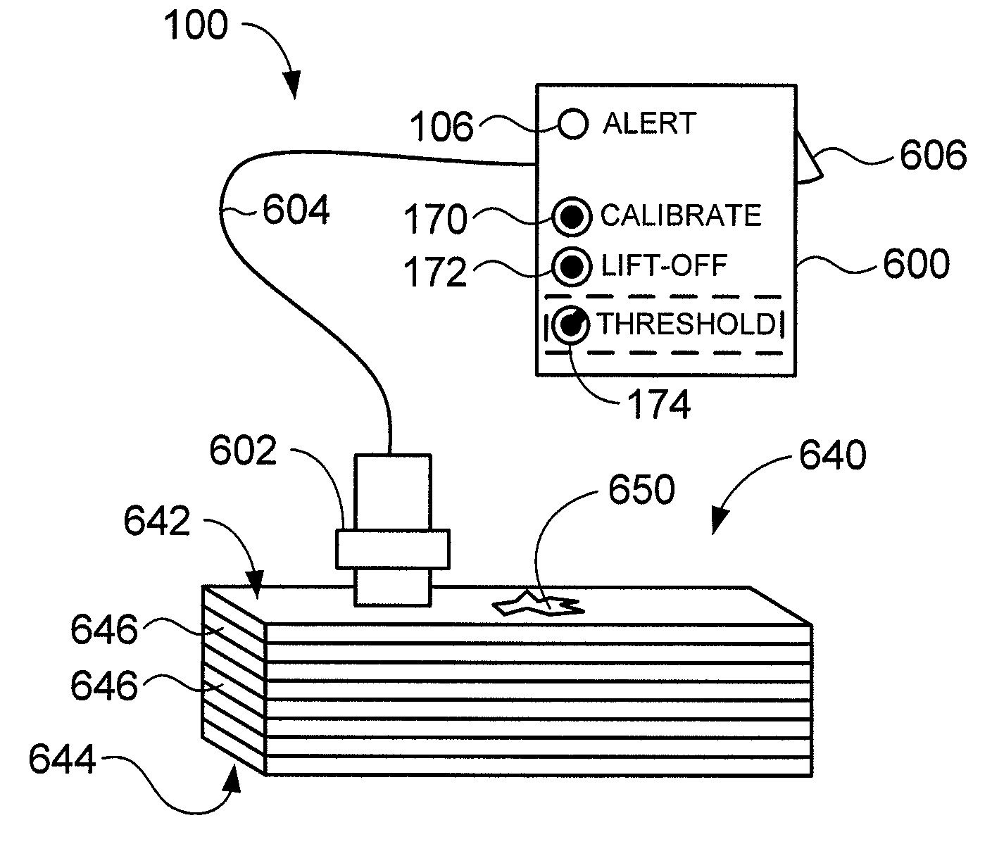
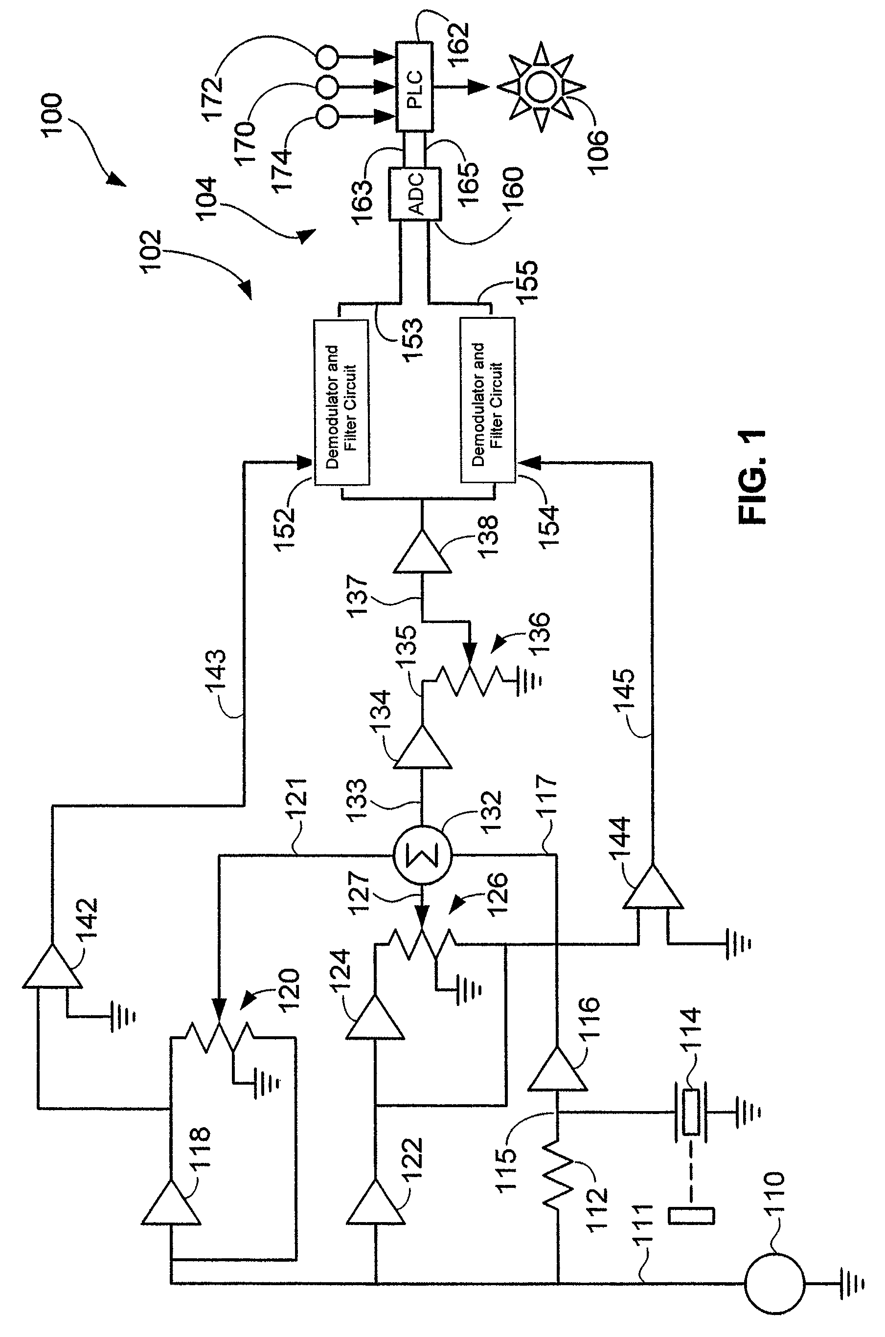
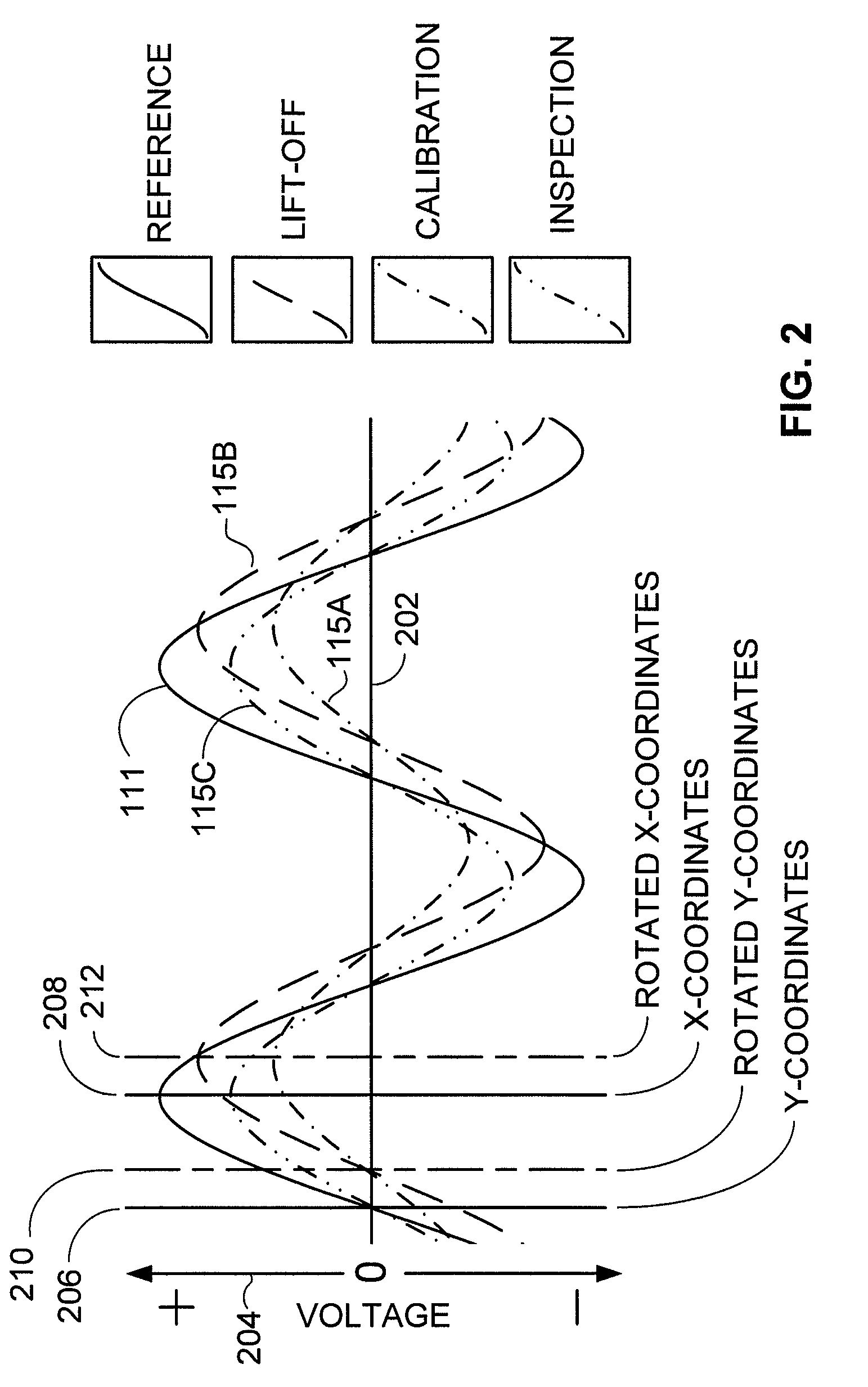
The invention relates to a method and system for inspecting structures using ultrasonic waves. The method involves calibrating the ultrasonic transducer with a structure portion free of defects, lifting the transducer from the first structure portion, and determining the coordinates of the lifted transducer. The calibration and lift-off coordinates are then rotated to a first axis. An indicator is activated if the rotated inspection coordinates are at least disposed above the first axis. The system includes an ultrasonic transducer and an electronic device with an indicator, such as a light source. The electronic device is in electrical contact with the ultrasonic transducer and can determine the impedance-plane coordinates of the transducer, determine if any of the coordinates exceed a preset threshold, and automatically activate the indicator if a defect is detected. The system can also automatically rotate the impedance-plane coordinates. The technical effects of the invention include improved accuracy and efficiency in inspecting structures using ultrasonic waves.

Problems solved by technology

Like any material disposed along the exterior of an aircraft, laminate composite materials are subject to damages during the service life of an aircraft.
In-flight collisions with birds and air-borne debris, and ground collisions involving loading and maintenance vehicles and equipment cause visible impact sites along the exterior of an aircraft.
Assessments and repairs of laminate composite materials represent significant challenges with regard to efficiencies in time, cost, and training.
Ground maintenance crews may be able to recognize impact sites along aircraft exteriors, but are typically not sufficiently trained or equipped to assess damages that may be associated with impact sites.
Damages within a composite aircraft component tend to initiate at impact sites and propagate into structures in expanding cone patterns.
Unfortunately, visible impact sites that represent mere superficial markings are not easily distinguished by visual inspection from those overlying significant internal damages.
Non-destructive inspection (NDI) devices are available so that inspections can reveal hidden sub-surface damages.
However, typical available technologies require considerable training and experience.
Consequences can be severe when such a decision is poorly made.
Trained NDI specialists and the complex equipment they may need to deploy are not typically immediately available at commercial aviation facilities.
If specialists are to be summoned every time an impact site along the exterior of an aircraft is noticed, flight delays will occur, and passengers may need to be re-routed and possibly accommodated with hotel rooms and meals.

Method used


Image

  • Simplified impedance plane bondtesting inspection
  • Simplified impedance plane bondtesting inspection
  • Simplified impedance plane bondtesting inspection

Examples


Embodiment Construction

[0020]The present invention now will be described more fully hereinafter with reference to the accompanying drawings, in which some, but not all embodiments of the invention are shown. Indeed, the invention may be embodied in many different forms and should not be construed as limited to the embodiments set forth herein; rather, these embodiments are provided so that this disclosure will satisfy applicable legal requirements. Like numbers refer to like elements throughout.

[0021]An inspection system 100 according to at least one embodiment of the invention is shown in FIG. 1. The inspection system includes an analog signal-processing portion 102 and a digital processing portion 104. With regard to the analog signal-processing portion 102 of the inspection system 100, an oscillator 110 produces a sinusoidal reference signal 111 that is applied to a combination of a resistor 112 and an ultrasonic transducer 114. When the ultrasonic transducer 114 is placed in contact or coupling with a...


PUM

PropertyMeasurementUnit
structureaaaaaaaaaa
impedance-plane calibrationaaaaaaaaaa
impedance-plane lift-off coordinatesaaaaaaaaaa

Abstract

An NDI system includes an ultrasonic transducer and an electronic device having an indicator, such as a light source. The electronic device energizes the transducer, receives sinusoidal signals from the transducer, determines impedance-plane coordinates corresponding to quadrature-phase separated components of the sinusoidal signals, and automatically activates the indicator if impedance-plane coordinates exceed a preset threshold. The system may be used in methods of inspecting layered structures such as composite aircraft components and repair patches applied to such structures.

Description

FIELD OF THE INVENTION[0001]Embodiments of the present invention relate generally to ultrasonic inspections of structures. More particularly, embodiments of the invention relate to systems and methods for non-destructive ultrasonic inspections of sub-surface portions of layered structures.BACKGROUND OF THE INVENTION[0002]Laminate composite materials are becoming increasingly common in the constructions of large aircraft. Typical laminate composite materials are composed of layered resin bonded graphite textiles. Like any material disposed along the exterior of an aircraft, laminate composite materials are subject to damages during the service life of an aircraft. In-flight collisions with birds and air-borne debris, and ground collisions involving loading and maintenance vehicles and equipment cause visible impact sites along the exterior of an aircraft. Assessments and repairs of laminate composite materials represent significant challenges with regard to efficiencies in time, cost...

Claims


Application Information

Patent Timeline
Patent Type & Authority Patents(United States)
IPC IPC(8): G01N29/09
CPCG01N29/09G01N29/30G01N29/4436G01N29/4445G01N29/4463G01N29/4454G01N2291/2694G01N2291/0231G01N2291/0258
Inventor KOLLGAARD, JEFFREY R.WOOD, NANCY L.
Owner THE BOEING CO
Learn More