

Dual direction exercise treadmill for simulating a dragging or pulling action with a user adjustable constant static weight resistance
- Summary
- Abstract
- Description
- Claims
- Application Information
AI Technical Summary
Benefits of technology
Problems solved by technology
Method used
Image

Examples
second embodiment
[0046]FIG. 5 is a side view of the moment arm weight resistance mechanism in the resting position. FIG. 6 is a side view of the moment arm weight resistance mechanism in a resistance position. FIG. 7 is a top view of an embodiment of the moment arm weight resistance mechanism of the invention. FIG. 8 is a side view of the embodiment of the moment arm weight resistance mechanism shown in FIG. 7. FIG. 9 is a side view of an alternate embodiment of the moment arm weight resistance mechanism of the invention. FIG. 10 is a sectional side view of the moment arm weight resistance mechanism shown in FIG. 3 in larger detail.
[0047]FIG. 11 is a sectional side view of a representative weight and weight adjusting drive that can be used with the present invention. FIG. 12 is a side view of the internal pulley and cable configuration between the resistance arm and the moment arm mechanism. FIG. 13 is a view of a representative control console and hand controller for the invention. FIG. 14 is a sid...
first embodiment
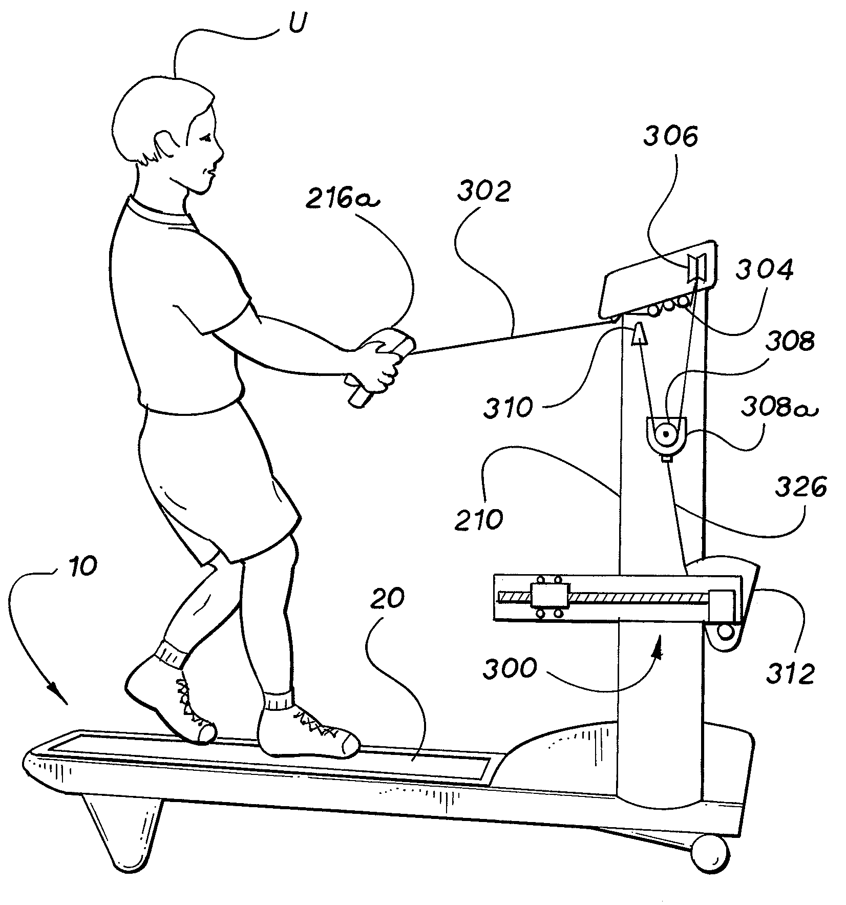
[0048]FIG. 15 is a side view, partly in section, of the invention operating in reverse dragging / pulling mode in an inclined position, showing the moment arm weight resistance mechanism and a hand grip or hand grip controller operatively attached to the weight resistance mechanism only via a flexible cable so as to have a freer range of motion, without resistance arm sections or linkages. FIG. 16 is a top view of an embodiment of the invention having a movable hand grip or hand grip controller operatively connected to the weight resistance mechanism and a fixed control console, illustrating the distinction between the movable hand grip controller and the fixed or unmovable console control. FIG. 17 is a top view of an embodiment of the invention showing controller features both on the movable resistance arm and the fixed console controller.
[0049]FIG. 18 is a side view, partly in section, of an alternate pneumatic or hydraulic weight resistance mechanism in the resting position. FIG. 1...
PUM
 Abstract
Description
Claims
Application Information