Dipping varnish-coated cooling shell of a housing for an electric machine

a technology for electric motors and cooling shells, which is applied in the direction of electrical equipment, dynamo-electric machines, supports/encloses/casings, etc., can solve the problems of corrosion, internal rusting of cooling channels, and the possibility of dipping varnish is further enhanced, so as to facilitate dipping and easy to assemble sealing

Inactive Publication Date: 2009-08-18
BAUMULLER NURNBERG GMBH
View PDF23 Cites 19 Cited by
  • Summary
  • Abstract
  • Description
  • Claims
  • Application Information

AI Technical Summary

Benefits of technology

[0011]According to an advantageous embodiment of the invention in which the housing jacket has plural housing jacket faces, in particular parallel end faces, the cooling channels are formed on at least a first housing jacket face with apertures which are freely accessible on the outside. Therefore because the cooling channels open freely on to a face of the housing jacket, upon dipping of the jacket into a varnish bath, the electro-dipping varnish can be applied via these cooling channels to the inner faces of the cooling channel system to be coated. Upon completion of the cathodic dipping process, the dipping liquid can escape quite quickly through the free apertures, or the housing jacket can be particularly easily emptied of the dipping liquid running out of these apertures.
[0012]The possibility of emptying the dipping varnish is further enhanced if on the opposing, preferably integrally cast-on housing jacket face one or more bores or other perforations are formed. These can also be used to fill the housing jacket with additional cathodic dipping liquid and to drain the said liquid. Advantageously, the bores are provided with female threads so that for the normal cooling long-term operation of the corresponding electric motor or generator, it is easy to assemble a sealing means on the integrally cast end face via sealing screws preferably provided with sealing rings.

Problems solved by technology

However, the problem of corrosion is not addressed, and this is serious in the case of an aluminium housing jacket cooled by water which may become contaminated with dirt and impurities.
There is a risk that then the aluminium may oxidise and corrode very rapidly.
This then leads to internal rusting of the cooling channels and rust particles can become detached and block the cooling channel system.

Method used


Image

  • Dipping varnish-coated cooling shell of a housing for an electric machine
  • Dipping varnish-coated cooling shell of a housing for an electric machine
  • Dipping varnish-coated cooling shell of a housing for an electric machine

Examples


Embodiment Construction

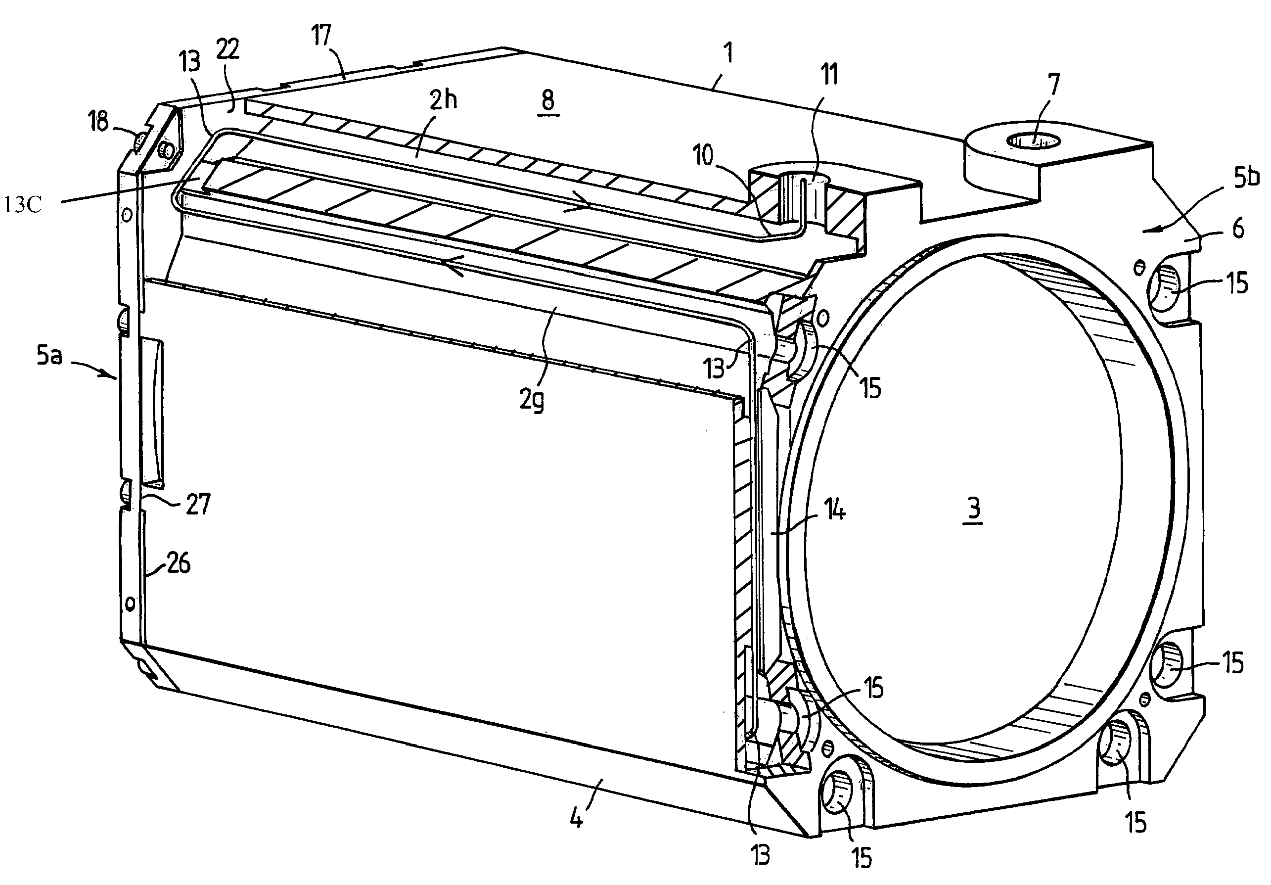
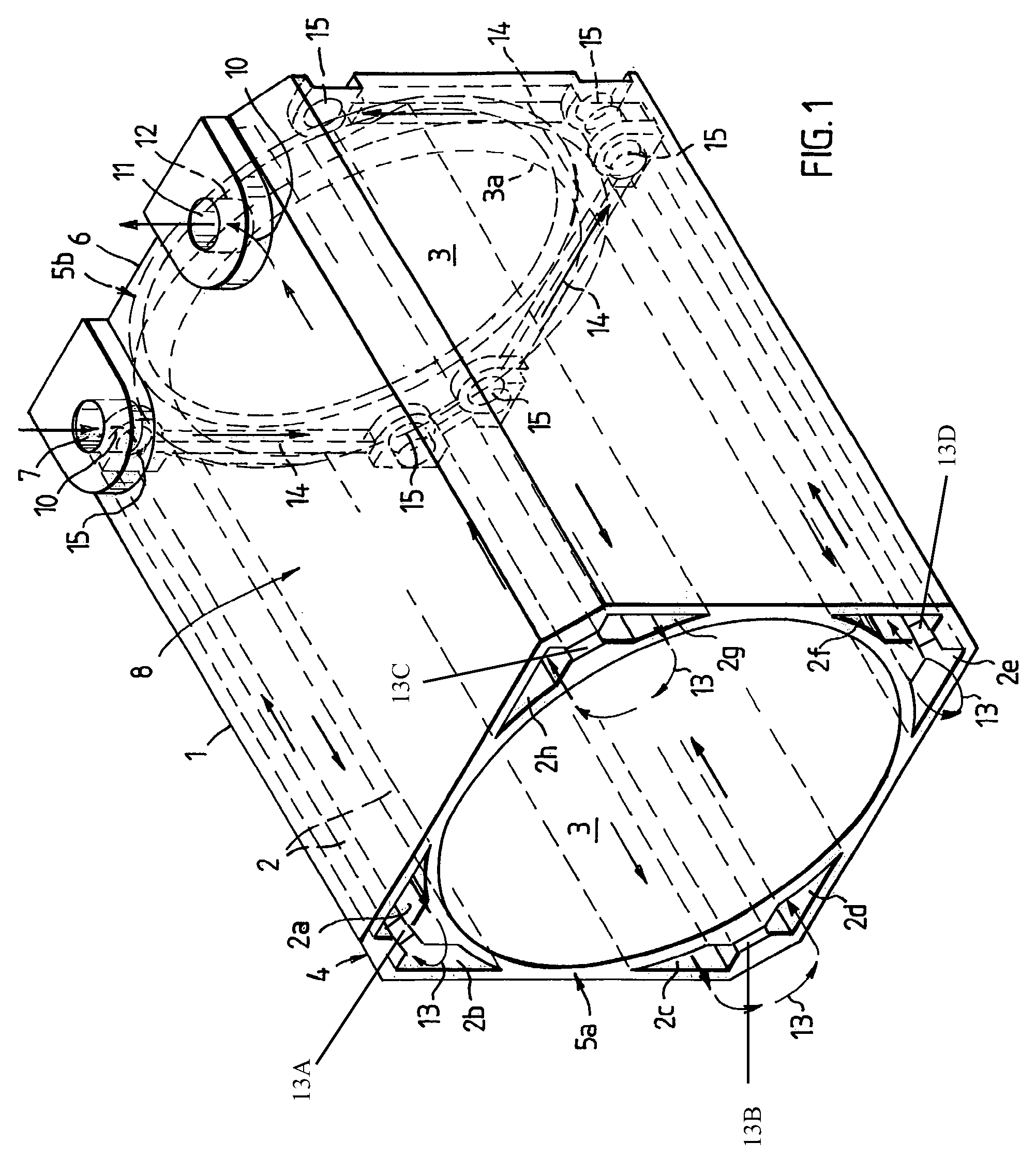
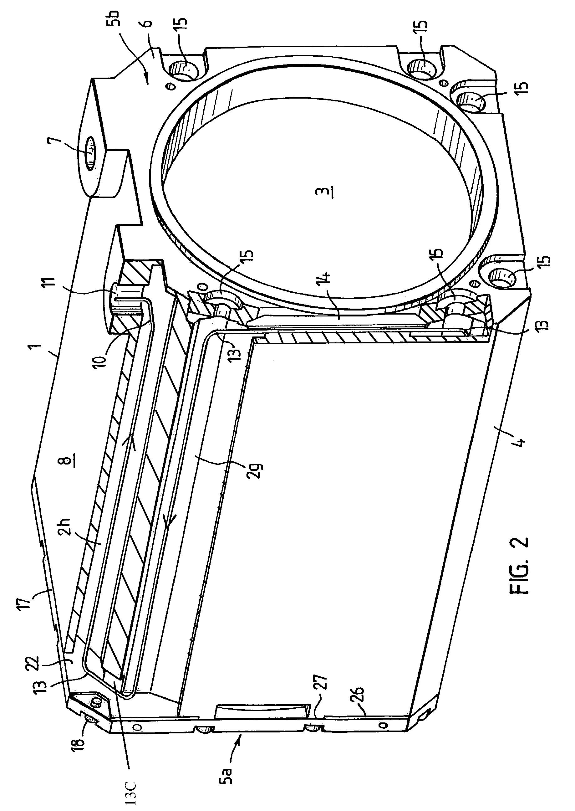
[0026]According to FIG. 1, the housing jacket 1 is manufactured as an integral aluminium casting with in all eight axially parallel cooling channels 2. The housing jacket 1 has in its interior a clear passage 3, which is symmetrical with respect to a hypothetical motor axis of rotation and which is used to receive a coaxial or concentric internal rotor / stator arrangement together with windings and winding overhang (as is also shown in FIG. 4). The cooling channels 2 extend parallel to the hypothetical machine axis of rotation (axially parallel) between a recessed contour 3a defining the passage 3 and the axially parallel outer wall 4 of the housing jacket 1. Two cooling channels 2 are provided, extending adjacent to one another, per quadrant of the circular circumference. Their ends are left open and freely accessible at a first housing jacket end face 5a of two parallel end faces 5a, 5b. As can also be deduced from FIG. 2, the cooling channels 2 end at the second end face 5b at a r...


PUM


Abstract

A coolable housing shell for an electric machine, which is produced as a cast part, accommodates a concentric interior rotor / stator arrangement, coils, and end windings, and comprises a clear, open, through passage that is embodied in a symmetric, concentric, and / or coaxial manner relative to an imaginary axis of rotation of the machine. Said housing shell is interspersed with one or several cooling channels so as to form a coolant circuit. The inner surfaces of the shell and the inner walls of the channel / s have a coating via a cathodic dipping varnish method.

Description

BACKGROUND OF THE INVENTION[0001]1. Field of the Invention[0002]The invention relates to a coolable housing jacket for an electric motor, which takes the form of a moulded part manufactured by casting. To receive a coaxial or concentric internal rotor / stator arrangement including windings and winding overhang, the housing jacket is formed with a through-passage which is symmetrical, concentric and / or coaxial with respect to a hypothetical motor axis of rotation. Cooling is realised by means of circulation of coolant through one or more cooling channels penetrating the housing jacket.[0003]2. Description of the Related Art[0004]For the prior art, we refer first to DE 199 49 140 A1, DE 199 39 760 A1, DE 199 39 013 A1, DE 196 48 134 A1, DE 196 24 519 A1, DE 42 43 716 A1, DE 39 41 474 A1 and U.S. Pat. No. 5,084,642 A.[0005]A generic electric motor with liquid cooling is described in DE 100 45 424. A housing jacket is formed hollow and is divided into plural channels through which coolan...

Claims


Application Information

Patent Timeline
Patent Type & Authority Patents(United States)
IPC IPC(8): H02K9/00H02K9/20H02K5/06H02K5/12H02K5/14H02K5/20H02K15/14
CPCH02K15/14H02K5/20H02K5/06H02K5/12H02K5/14B25F5/008H02K5/203
Inventor WEHNER, HANS-JURGENSONNAUER, GUNTER
Owner BAUMULLER NURNBERG GMBH
Why Eureka
Try Eureka