Low-power clock gating circuit

Inactive Publication Date: 2009-08-18
ELECTRONICS & TELECOMM RES INST
View PDF6 Cites 56 Cited by
  • Summary
  • Abstract
  • Description
  • Claims
  • Application Information

AI Technical Summary

Benefits of technology

[0016]The present invention relates to a low-power clock gating circuit using a Multi-Threshold CMOS (MTCMOS) technique. The present invention is directed to a low-power clock gating circuit comprising a latch circuit and an AND gate circuit configured by the MTCMOS technique, in which power consumption caused by leakage current is reduced in a sleep mode, and supply of a clock to a targeted logic circuit is prevented in an active mode.
[0017]As described above, a conventional clock gating circuit using single threshold voltage devices cannot both block a clock and reduce power consumption caused by leakage current. To solve this problem, the present invention provides a low-power clock gating circuit including a latch circuit and an AND gate using an MTCMOS technique. The present invention is directed to a clock gating circuit which retains data without leakage current in a sleep mode, reduces power consumption caused by leakage current, and prevents a clock from being supplied to an unused targeted logic circuit in an active mode for reduction of power consumption in the targeted logic circuit.

Problems solved by technology

As described above, a conventional clock gating circuit using single threshold voltage devices cannot both block a clock and reduce power consumption caused by leakage current.

Method used


Image

  • Low-power clock gating circuit
  • Low-power clock gating circuit
  • Low-power clock gating circuit

Examples


Embodiment Construction

[0034]Hereinafter, preferred embodiments of the present invention will be described in detail with reference to the accompanying drawings. The embodiments of the present invention, however, may be changed into several other forms, and the scope of the present invention should not be construed to be limited to the following embodiments. The embodiments of the present invention are intended to more entirely explain the present invention to those skilled in the art.

[0035]In general, transistors include transistors having a low threshold voltage and transistors having a high threshold voltage. 130 nm transistors operating at 1.2V have a low threshold voltage of about 0.24V and a high threshold voltage of about 0.44V. In the description below, a signal inverting circuit may be simply referred to as an inverting circuit.

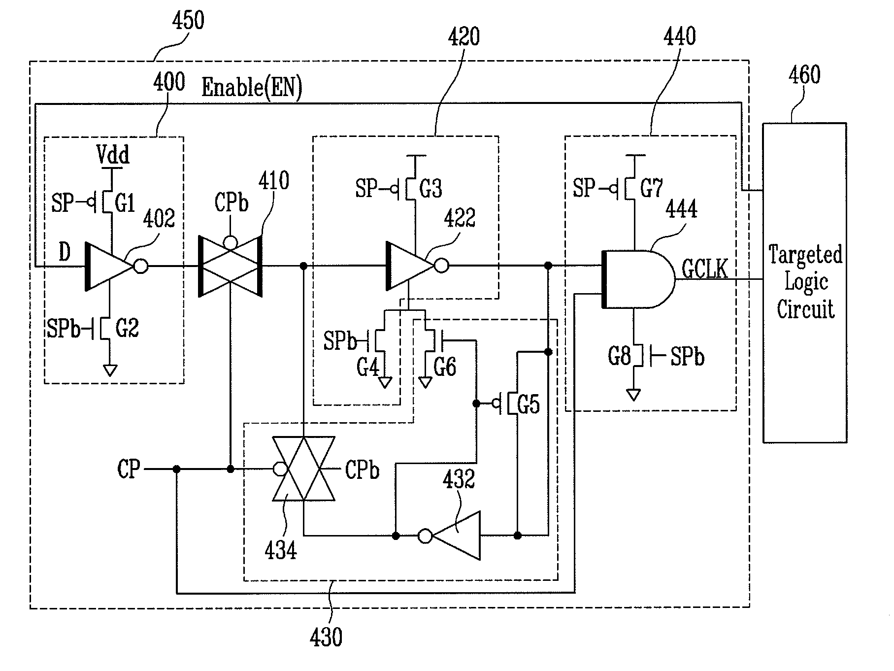
[0036]FIG. 4 illustrates a clock gating circuit using an MTCMOS technique according to the present invention, FIG. 5a illustrates a transmission gate circuit comprising lo...


PUM


Abstract

Provided is a low-power clock gating circuit using a Multi-Threshold CMOS (MTCMOS) technique. The low-power clock gating circuit includes a latch circuit of an input stage and an AND gate circuit of an output stage, in which power consumption caused by leakage current in the clock gating circuit is reduced in a sleep mode, and supply of a clock to a unused device of a targeted logic circuit is prevented by the control of a clock enable signal in an active mode, thereby reducing power consumption. The low-power clock gating circuit using an MTCMOS technique uses devices having a low threshold voltage and devices having a high threshold voltage, which makes it possible to implement a high-speed, low-power circuit, unlike a conventional clock gating circuit using a single threshold voltage.

Description

CROSS-REFERENCE TO RELATED APPLICATION[0001]This application claims priority to and the benefit of Korean Patent Application No. 2006-122514, filed Dec. 5, 2006, and No. 2007-54320, filed Jun. 4, 2007, the disclosure of which is incorporated herein by reference in its entirety.BACKGROUND[0002]1. Field of the Invention[0003]The present invention relates to a clock gating circuit capable of blocking a clock supplied in an active mode when a device in a targeted logic circuit does not operate and retaining data without leakage current in a sleep mode, by using a Multi-Threshold CMOS (MTCMOS) technique.[0004]The present invention has been produced from the work supported by the IT R&D program of MIC (Ministry of Information and Communication) / IITA (Institute for Information Technology Advancement) [2006-S-006-01, Components / Module technology for Ubiquitous Terminals] in Korea.[0005]2. Discussion of Related Art[0006]FIG. 1 illustrates a conventional clock gating circuit using a single th...

Claims


Application Information

Patent Timeline
Patent Type & Authority Patents(United States)
IPC IPC(8): H03K3/289
CPCH03K3/0375
Inventor LEE, DAE WOOYANG, YIL SUKCHUN, IK JAELYUH, CHUN GIROH, TAE MOONKIM, JONG DAE
Owner ELECTRONICS & TELECOMM RES INST
Why Eureka
Try Eureka