
Image processing apparatus, image forming apparatus, printer driver, image processing method and computer-readable storage medium

a technology of image processing and printer, applied in the direction of image enhancement, digitally marking record carriers, instruments, etc., can solve the problems of increasing the production cost of the ink-jet head, negligible noise generated by the ink-jet printer during recording, and large size of the ink-jet printer as a whole, so as to achieve satisfactory picture quality

Active Publication Date: 2009-08-18
RICOH KK
View PDF12 Cites 10 Cited by
  • Summary
  • Abstract
  • Description
  • Claims
  • Application Information

AI Technical Summary

Benefits of technology

This patent describes an image processing system that can improve the quality of images created by using dots. The system can adjust the size of dots in certain areas of the image, such as around edges or borders, to create a smoother and more detailed image. This can be particularly useful for low-resolution printing or high-speed recording. The system can also convert the image data into a different format, such as a bitmap, to reduce data transfer time between the image forming apparatus and the host unit. Overall, this patent provides a way to create high-quality images using dots while optimizing image quality and speed.

Problems solved by technology

In addition, noise generated by the ink-jet printer during the recording is negligibly small.
However, the size of the ink-jet printer as a whole becomes large because the ink-jet head of the line type ink-jet printer is large.
Furthermore, in order to carry out the recording at a high resolution, the nozzles must be arranged at a high density, thereby increasing the production cost of the ink-jet head.
However, particularly when the ink-jet printer records the image on plain paper, picture quality deteriorations peculiar to the ink-jet recording, such as color reproducibility, durability, light resistance, ink drying characteristic (fixing characteristic), feathering, color bleeding and duplex recording characteristic of the image, become conspicuous.
Moreover, when an attempt is made to carry out a high-speed recording with respect to the plain paper, it is extremely difficult to carry out the recording while satisfying all of these characteristics which affect the picture quality.
However, the ruggedized characteristic, such as the light resistance and water resistance of the image, obtained by use of the dye-based ink is poorer than that obtained by use of an ink which uses the pigment as the coloring agent.
But a satisfactory water resistance cannot be obtained when the plain paper is used.
However, it is difficult to simultaneously improve the other characteristics which affect the picture quality.
It is difficult to obtain a high image tone, a sufficient color generation, a high color reproducibility and the like, particularly when carrying out a high-speed recording with respect to the plain paper.
As a result, it is difficult to simultaneously obtain satisfactory ink drying characteristic (fixing characteristic), feathering, color bleeding and duplex recording characteristic of the image.
The nozzle density is limited by the processing accuracy of the nozzle, ink chamber, flow passage, actuator and the like.
However, particularly in the case of the piezoelectric ink-jet printer using the piezoelectric element, the nozzle density itself is low, and for this reason, the resolution of the image inevitably becomes low when the single-path interlacing is employed to improve the recording speed.
The multi-level representation method is effective in the case of images such as photographs, but are virtually ineffective in the case of graphics and characters.
Accordingly, problems peculiar to the low resolution occur in the case of a bi-level image such as graphics and characters, and particularly in the case of the characters, the quality of the characters becomes poor and the characters become difficult to read.
The j aging portion becomes particularly conspicuous at the time of the low-resolution recording and deteriorates the quality of the characters.
However, when recording at 100% duty with respect to the recording paper, the solid adhering amount per unit area needs to be on the order of approximately several tens of ng / m2, and problems are introduced from the point of view of the ink fixing characteristic (drying characteristic).
Thus, the recording method proposed in the Japanese Laid-Open Patent Application No.6-171072 is not suited for the high-speed recording.
Furthermore, at the boundary portion of the colors, the color bleeding is easily generated in the ink drop state between the adjacent recorded dots due to the large contact angle of the ink.
As a result, the penetrating ink becomes visible on the other side of the plain paper, thereby making the recording unsuited for application to the duplex recording.
Therefore, the recording methods proposed in the Japanese Laid-Open Patent Applications No.6-171072 and No.2000-355159 cannot realize a sufficiently satisfactory picture quality when carrying out the high-speed recording with respect to the plain paper using the pigment-based ink.
On the other hand, the methods proposed in the Japanese Patents No.2886192 and No.3029533 for correcting the jaggy portion cannot be applied as they are to the ink-jet printer for the purposes of improving the picture quality when recording the image having the low resolution using the ink which generates little feathering.
But in the case of the ink-jet printer, the spreading of the ink dot is large compared to that of the toner dot in the laser printer, and the time required to form the dots is large compared to the LED printers and the laser printers.
Consequently, it is difficult to vary the dot size among a large number of dot sizes by varying the number, length and the like of driving pulses during the driving period, and it is only possible to vary the dot size among several sizes at the most.
Furthermore, the dot can only be formed at an approximately predetermined position within one pixel due to similar reasons, and it is difficult to freely vary the position of the dot within one pixel as is possible in the case of the LED printers and laser printers.
Therefore, the methods proposed in the Japanese Patents No.2886192 and No.3029533 for correcting the jaggy portion cannot be applied as they are to the ink-jet printer for the purposes of improving the picture quality.
However, the anti-aliasing varies the dots in an extremely large number of gradation levels at the contour portion.
For this reason, a highly accurate smoothing can be realized by the anti-aliasing, but the required processes are extremely complex and time-consuming.
Consequently, the anti-aliasing is unsuited for application to the ink-jet printer which is required to produce a high throughput.
In addition, when the recording is made by varying the dot size in the ink-jet printer, there is a problem in that the dot position on the recording paper becomes different depending on the dot size.
Therefore, even when an attempt is made to improve the picture quality by correcting the contour portion by the small dots, the small dots are not formed at the desired positions on the recording paper, and there is a possibility of deteriorating the picture quality rather than improving the picture quality.

Method used


Image

  • Image processing apparatus, image forming apparatus, printer driver, image processing method and computer-readable storage medium
  • Image processing apparatus, image forming apparatus, printer driver, image processing method and computer-readable storage medium
  • Image processing apparatus, image forming apparatus, printer driver, image processing method and computer-readable storage medium

Examples


first experiment

(First Experiment)

[0290]The font data added with the small ink drops in the manner described above were printed on plain paper using the ink-jet head under the following conditions, and the picture quality (character quality) was evaluated.[0291]Head: 384 nozzles / color[0292]Nozzle pitch=84 ìm (corresponding to 300 dpi)[0293]Image Resolution: 300 dpi[0294]Dot Size: Large ink drop=120 ìm, Small ink drop=40 ìm[0295]Character: MS Mincho, Font size=6, 10, 12, 20, 30, 50 and 80 points[0296]Jaggy Correction Method: Change depending on inclination of oblique line portion (see Table 1 below)[0297]Printing Method: Path number (number of scans forming one line)=1, No interlacing[0298]Paper: Plain paper (My Paper TA (product name)) manufactured by Ricoh Company, Ltd.

[0299]

TABLE 1Inclination of Oblique LineJaggy Correction Method1 / 1None1 / 2, 2 / 1FIG. 18C1 / 3, 3 / 1FIG. 17B

[0300]For comparison purposes, a first comparison example in which no jaggy correction is made and the printing is made solely by ...

second experiment

(Second Experiment)

[0306]The font data added with the small ink drops in the manner described above were printed on plain paper using the ink-jet head under the following conditions, and the picture quality (character quality) was evaluated.[0307]Head: 384 nozzles / color[0308]Nozzle pitch=84 ìm (corresponding to 300 dpi)[0309]Image Resolution: 300 dpi[0310]Dot Size: Large ink drop=120 ìm, Medium ink drop=70 ìm, Small ink drop=40 ìm[0311]Character: MS Mincho, Font size=6, 10, 12, 20, 30, 50 and 80 points[0312]Jaggy Correction Method: Change depending on inclination of oblique line portion (see Table 2 below)[0313]Printing Method: Path number (number of scans forming one line)=1, No interlacing[0314]Paper: Plain paper (My Paper TA (product name)) manufactured by Ricoh Company, Ltd.

[0315]

TABLE 2Inclination of Oblique LineJaggy Correction Method1 / 1None1 / 2, 2 / 1FIG. 18C1 / 3, 3 / 1FIG. 32B

[0316]For comparison purposes, a first comparison example in which no jaggy correction is made and the pri...


PUM

PropertyMeasurementUnit
grain diameteraaaaaaaaaa
diameteraaaaaaaaaa
voltageaaaaaaaaaa

Abstract

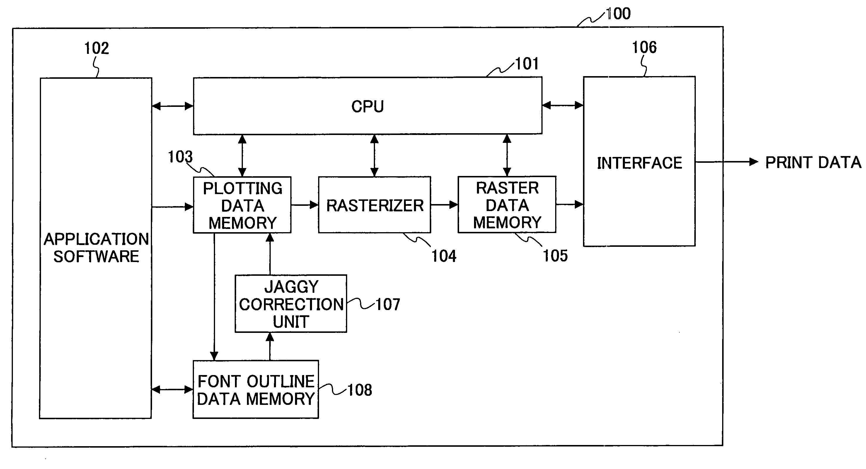
An image forming apparatus forms an image by a plurality of dots, by forming a periphery of a stepped transition portion of a contour portion of at least a character and / or graphics of the image by dots having a smaller size than dots forming portions other than the stepped transition portion, and determining a method of forming the dots having the smaller size depending on an inclination of the contour portion.

Description

TECHNICAL FIELD[0001]The present invention generally relates to-image processing apparatuses, image forming apparatuses, printer drivers and image processing methods, and more particularly to an image processing apparatus, an image forming apparatus, a printer driver and an image processing method which are suited for improving a picture quality at a low resolution. The present invention also relates to a computer-readable storage medium which stores a computer program for causing a computer to carry out an image processing suited for improving the picture quality at a low resolution.BACKGROUND ART[0002]An ink-jet printer is used in various kinds of image forming apparatuses (or image recording apparatuses) such as printers, facsimile machines and copying machines. The ink-jet printer can record at a high speed, and does not require a special fixing process with respect to the so-called plain paper. In addition, noise generated by the ink-jet printer during the recording is negligib...

Claims


Application Information

Patent Timeline
Patent Type & Authority Patents(United States)
IPC IPC(8): G06F15/00G06K1/00H04N1/60G06K15/02B41J2/01B41J2/21B41J2/485B41M5/00G06K15/12
CPCB41J2/21G06K15/102G06K15/02B41J2002/14411G06K2215/006
Inventor KIMURA, TAKASHI
Owner RICOH KK
Learn More