Hologram recording device and phase mask having a diffusing pattern with a minimum unit in relation to a minimum unit of a spatial modulator

a technology of spatial modulator and recording device, which is applied in the field of ho, can solve the problems of deteriorating ber and increasing noise, and achieve the effects of preventing s/n degradation, suppressing the dc component of signal light, and improving ber

Inactive Publication Date: 2009-08-18
SONY CORP
View PDF5 Cites 8 Cited by
  • Summary
  • Abstract
  • Description
  • Claims
  • Application Information

AI Technical Summary

Benefits of technology

[0009]The present invention has been devised in view of the above situation. It is desirable to provide a phase mask and a hologram recording device using the phase mask that can suppress the DC component of signal light without degrading the S / N of a reproduced image, and improve a bER.
[0011]Thus, in the present invention, by setting the minimum unit of the light diffusing pattern formed in the phase mask to a natural number of times the minimum unit of display data of the spatial modulator, the boundary of the light diffusing pattern of the phase mask is prevented from lying on the inside of the minimum unit of display data of the spatial modulator, and therefore the boundary part of the pattern of the phase mask does not appear inside a data block. It is thereby possible to prevent degradation in the S / N of a recording image without noise caused by the phase mask being superimposed on the signal light. This has been confirmed by experiment. It is therefore possible to suppress the DC component of signal light without degrading the S / N of a reproduced image, and improve a bER.
[0012]According to the present invention, by setting the minimum unit of the light diffusing pattern formed in the phase mask to a natural number of times the minimum unit of display data of the spatial modulator, the boundary of the light diffusing pattern of the phase mask is prevented from lying on the inside of the minimum unit of display data of the spatial modulator. It is therefore possible to suppress the DC component of signal light without degrading the S / N of a reproduced image, improve a bER, and improve recording density by effectively using the dynamic range of a hologram recording medium.

Problems solved by technology

When the phase mask for removing the DC component from the signal light is introduced into a signal light optical system as described above in order to prevent the signal light concentrated too much on the hologram recording material from decreasing efficiency of use of the hologram recording material and decreasing an S / N, the problem caused by the DC component of the signal light is solved, whereas it is known that noise is increased instead because noise resulting from the introduction of the phase mask is superimposed on the signal light.
This is caused by superimposition of an intensity component on the image of the diffuser which inherently has only a phase component due to effects of aberration of a hologram recording and reproducing optical system and incompleteness of hologram recording itself.
When the intensity variations are superimposed on the data pattern of the signal light, it presents a problem in reading data, and deteriorates a bER.

Method used


Image

  • Hologram recording device and phase mask having a diffusing pattern with a minimum unit in relation to a minimum unit of a spatial modulator
  • Hologram recording device and phase mask having a diffusing pattern with a minimum unit in relation to a minimum unit of a spatial modulator
  • Hologram recording device and phase mask having a diffusing pattern with a minimum unit in relation to a minimum unit of a spatial modulator

Examples


first embodiment

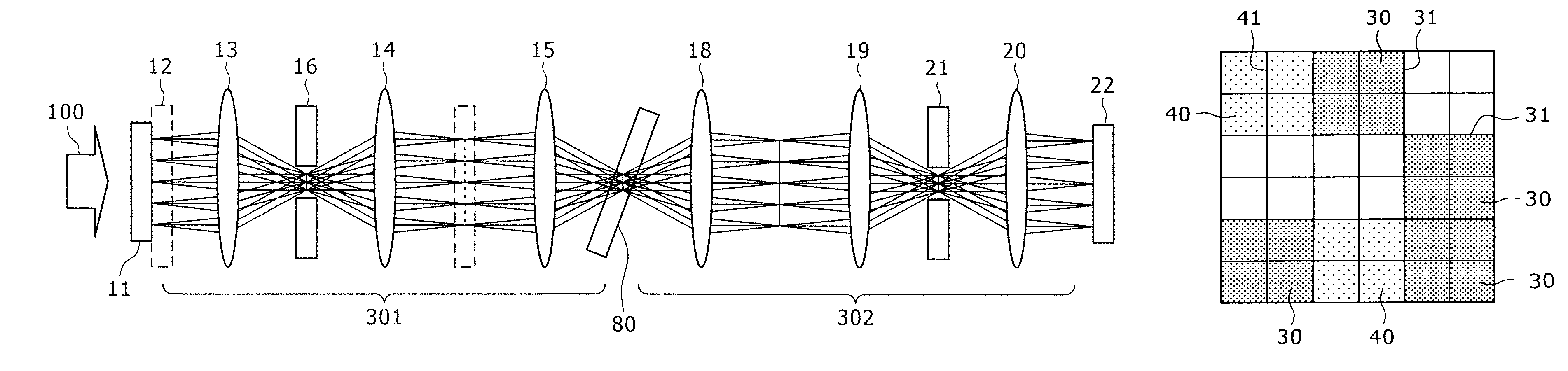
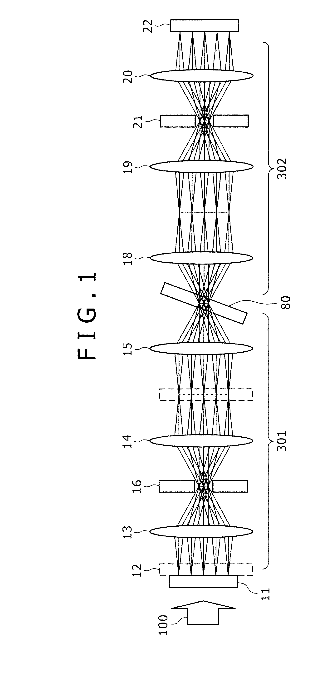
[0024]FIG. 1 is a block diagram showing the configuration of principal parts of a hologram recording device according to the present invention. The hologram recording device includes a signal light optical system 301 for recording and a signal light optical system 302 for reproduction. The recording signal light optical system 301 has a spatial modulator (SLM) 11, a phase mask 12 disposed at a position adjacent to the SLM 11, lenses 13, 14, and 15 forming the signal light optical system, and a high-frequency cutoff aperture 16 inserted between the lenses 13 and 14 to remove unnecessary light. A part represented by a broken line in the figure (phase mask) will be described later. The reproduction signal light optical system 302 has lenses 18, 19, and 20 forming the reproduction signal light optical system, a high-frequency cutoff aperture 21 inserted between the lenses 19 and 20 to remove unnecessary light, and an image sensor 22 for receiving reproduced signal light and thereby obta...

third embodiment

[0035]Accordingly, a light diffusing pattern is not created in parts of the phase mask which parts correspond to other than the data area of the SLM in the This prevents degradation in image quality due to insertion of the phase mask in the alignment mark, and thereby prevents decrease in accuracy of recognition of the alignment mark. For example, a light diffusing pattern is created in only an area of the phase mask which area corresponds to a part 91 (corresponding to a data display area of the SLM) shown in FIG. 6, and the pattern is not created in other parts.

[0036]According to the third embodiment, by creating the light diffusing pattern of the phase mask in only the area corresponding to the data page display area 91 of the SLM, and not creating the light diffusing pattern in other areas (the alignment mark 90), decrease in the accuracy of recognition of the alignment mark is prevented. It is thereby possible to maintain accuracy of positioning used in image processing at a t...


PUM


Abstract

A hologram recording device for recording interference fringes between reference light and signal light modulated by data displayed in a spatial modulator in a hologram recording material, the hologram recording device including a phase mask for diffusing light, the phase mask being disposed in an optical system that the signal light passes, wherein a minimum unit of a light diffusing pattern formed in the phase mask is a natural number of times a minimum unit of display data of the spatial modulator.

Description

CROSS REFERENCES TO RELATED APPLICATIONS[0001]The present invention contains subject matter related to Japanese Patent Application JP 2005-094158 filed with the Japanese Patent Office on Mar. 29, 2005, the entire contents of which being incorporated herein by reference.BACKGROUND OF THE INVENTION[0002]The present invention relates to a hologram recording device for recording interference fringes between signal light and reference light on a hologram recording medium, and particularly to a phase mask for suppressing the DC component of the signal light.[0003]A holographic data storage system has recently been proposed which records and reproduces a large volume of data using hologram technology for volume-recording interference fringes between signal light spatially modulated by information and reference light on a hologram recording material.[0004]In a conventional holographic data storage system, coherent laser light 50 emitted from a light source (not shown) is split into signal l...

Claims


Application Information

Patent Timeline
Patent Type & Authority Patents(United States)
IPC IPC(8): G02B5/32
CPCG03H1/16G11C13/042G11B7/1392G03H2225/55G11B7/00781G11B7/0065G11B20/10
Inventor KANESAKA, TOMOKIKIHARA, NOBUHIROBABA, SHIGEYUKIYAMATSU, HISAYUKIEZURA, MEGUMI
Owner SONY CORP
Why Eureka
Try Eureka