Method and circuit for adaptive control of the bandwidth of a carrier recovery loop in radio transmission systems

a carrier recovery loop and adaptive control technology, applied in the field of radio transmission systems, can solve the problems of low phase noise (pn), low phase noise (lopn), constant irreducible bit error rate (ber), etc., and achieve the effect of improving the ber value and improving the system ber valu

Inactive Publication Date: 2008-10-28
ALCATEL LUCENT SAS
View PDF4 Cites 0 Cited by
  • Summary
  • Abstract
  • Description
  • Claims
  • Application Information

AI Technical Summary

Benefits of technology

[0010]It is therefore an object of the present invention to overcome the above mentioned prior art drawbacks. This objective is achieved by the solution proposed by the present invention according to which by means of adaptively changing the transfer function of the PLL according to the signal to noise ratio (SNR) of the received signal, the BER of the system is improved. In fact, based on knowing the LOPN and estimating the amount of AWGN, it becomes possible to adaptively find the best bandwidth of the PLL, leading eventually to a substantial improvement in BER values.

Problems solved by technology

A particularly critical issue in bandwidth-efficient QAM systems is the phase noise (PN) of the local oscillators (LO) which are used to convert the modulated signal from IF to RF and vice versa.
Together with other noise-like degrading effects, LO—phase noise (LOPN) gives rise to a constant irreducible bit error rate (BER) independently from the power of the received signal.
However, the higher the radio frequency is, the more difficult it is to design and to produce a local oscillator with low phase noise.
Consequently the first solution may become considerably expensive, taking into account in particular the fact that at present the radio frequencies that are being used are growing higher and higher in value (e.g. up to 90 GHz).
However, there are two particular limits in achieving wide bandwidth for the PLL.
One such limitation is the introduction of an additional source of phase noise which is due to the phase estimator error introduced by the modulated signal itself; this additional phase noise—that depends also from the quality of the received signal level and from the amount of the additive white gaussian noise (AWGN)—must, as much as possible, remain much lower than the original one.
The second limit is the loop electrical delay.
It turns out that a long loop electrical delay makes it impossible to go beyond a certain bandwidth, because the phase transfer function of the PLL approaches levels close to instability.
However, taking into account that the optimum bandwidth of the PLL depends on the signal to noise ratio of the received signal, then the choice of a fixed bandwidth cannot be considered an “optimum” solution because the signal to noise ratio can change depending on the circumstances.

Method used


Image

  • Method and circuit for adaptive control of the bandwidth of a carrier recovery loop in radio transmission systems
  • Method and circuit for adaptive control of the bandwidth of a carrier recovery loop in radio transmission systems
  • Method and circuit for adaptive control of the bandwidth of a carrier recovery loop in radio transmission systems

Examples


Embodiment Construction

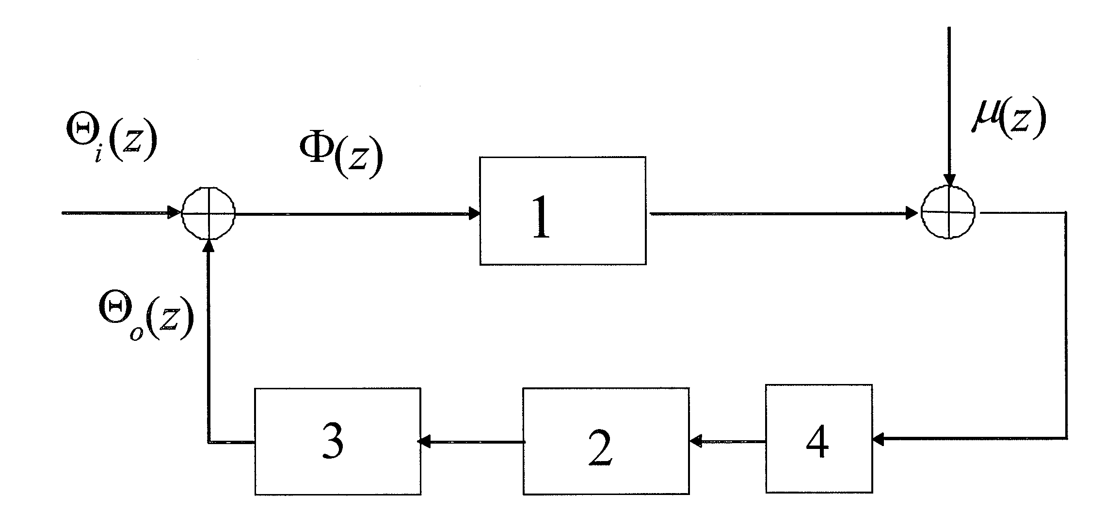
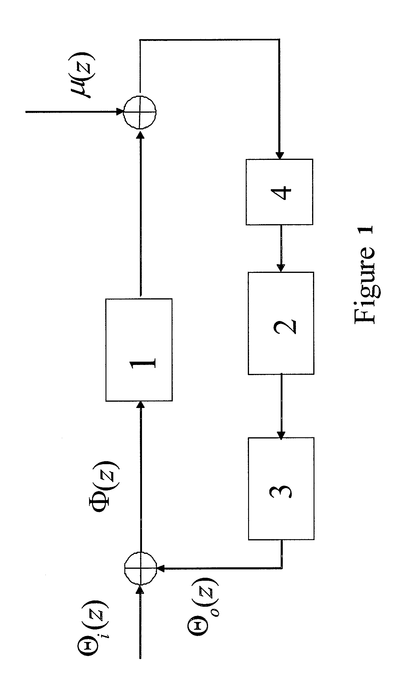
[0020]There are various known arrangements for PLLs, however, without loss of generality, it can be considered that the basic structure of a PLL can be represented in the block diagram of FIG. 1 wherein the PLL circuit comprises a phase detector 1, a loop filter 2, a voltage controlled oscillator 3 and an optional pure delay 4, the latter representing the undesired effect of a delay present in the loop, for example, due to a decision delay in a decision feedback loop.

[0021]Furthermore the additional source of phase noise is modeled by μ(k) which, as mentioned further above, is due to the phase estimator error introduced by the modulated signal itself, depending also from the amount of AWGN.

[0022]The input Φ(z) to the phase detector 1 is the difference between two signals, namely an input signal having a phase Θi(z) and an output signal fed-back to the input of the phase detector 1 having a phase Θo(z).

[0023]In the following, for the sake of simplicity, it is assumed that the system ...


PUM


Abstract

A method for adaptively controlling bandwidth of a carrier recovery loop in radio transmission systems, wherein the phase error in a PLL is adjusted to a minimum level by means of a loop filter incorporated in said PLL. The phase noise value in the local oscillator is determined and the value of the additive white gaussian noise in the PLL is estimated. Next these values are applied in a predetermined mathematical relationship indicative of the phase error in said PLL in such a manner that the desired wavelength of the PLL can be determined by corresponding to a minimum value of the phase error.

Description

FIELD OF THE INVENTION[0001]The present invention relates to a radio transmission system. More particularly the invention relates to a circuit and a method for the control of the bandwidth of a carrier recovery loop in such radio transmission systems.BACKGROUND OF THE INVENTION[0002]In order to make efficient use of the microwave radio spectrum, state-of-art digital point-to-point radio systems employ highly bandwidth-efficient modulation techniques. At present, certain known commercial systems employ 128 QAM signal constellation, nevertheless some 512 QAM prototypes are currently being field-tested. For the sake of clarity it is to be noted that “QAM” stands for Quadrature Amplitude Modulation which is a well known amplitude modulation scheme in which amplitude modulation is performed by two separate signals of two sinusoidal carriers having the same amplitude and frequency but being in phase quadrature, the modulated signals are then added for transmission on a single channel.[000...

Claims


Application Information

Patent Timeline
Patent Type & Authority Patents(United States)
IPC IPC(8): H04L27/00H03D3/18H03D3/24H03L7/093
CPCH03L7/093H04L27/0014H04L2027/0055H04L2027/0069H04L2027/0081
Inventor VALTOLINA, ROBERTOBRIOSCHI, MASSIMO
Owner ALCATEL LUCENT SAS
Why Eureka
Try Eureka