Method and circuit for adaptive control of the bandwidth of a carrier recovery loop in radio transmission systems
- Summary
- Abstract
- Description
- Claims
- Application Information
AI Technical Summary
Benefits of technology
Problems solved by technology
Method used
Image
Examples
Embodiment Construction
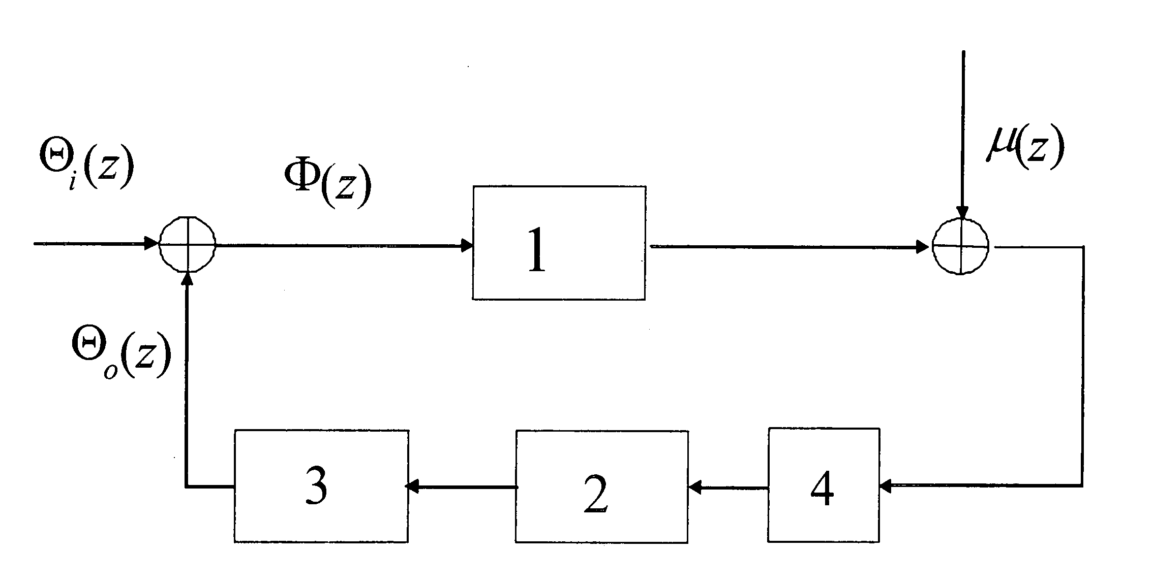
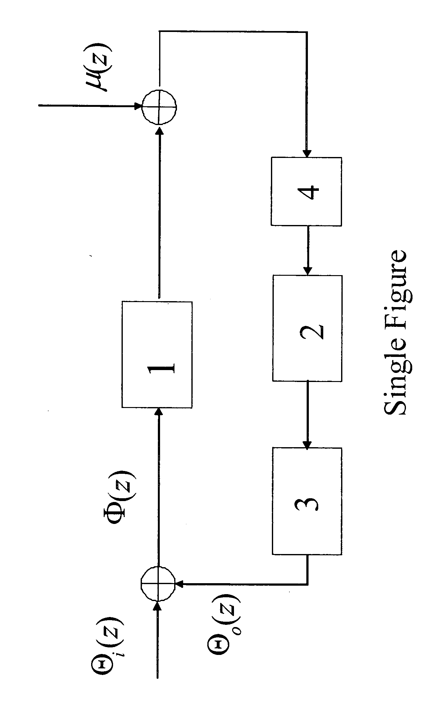
[0020] There are various known arrangements for PLLs, however, without loss of generality, it can be considered that the basic structure of a PLL can be represented in the block diagram of the figure wherein the PLL circuit comprises a phase detector 1, a loop filter 2, a voltage controlled oscillator 3 and an optional pure delay 4, the latter representing the undesired effect of a delay present in the loop, for example, due to a decision delay in a decision feedback loop. Furthermore the additional source of phase noise is modeled by μ(k) which, as mentioned further above, is due to the phase estimator error introduced by the modulated signal itself, depending also from the amount of AWGN.
[0021] The input Φ(z) to the phase detector 1 is the difference between two signals, namely an input signal having a phase Θi(z) and an output signal fed-back to the input of the phase detector 1 having a phase Θo(z).
[0022] In the following, for the sake of simplicity, it is assumed that the sys...
PUM
 Abstract
Description
Claims
Application Information
 - R&D
- Intellectual Property
- Life Sciences
- Materials
- Tech Scout
- Unparalleled Data Quality
- Higher Quality Content
- 60% Fewer Hallucinations
Browse by: Latest US Patents, China's latest patents, Technical Efficacy Thesaurus, Application Domain, Technology Topic, Popular Technical Reports.
© 2025 PatSnap. All rights reserved.Legal|Privacy policy|Modern Slavery Act Transparency Statement|Sitemap|About US| Contact US: help@patsnap.com


