System and method for performance monitoring and reconfiguring computer system with hardware monitor
a computer system and monitor technology, applied in error detection/correction, multi-programming arrangements, instruments, etc., can solve the problems of inability to apply code tuning on the code level, whether hardware is causing a performance bottleneck directly, and the performance cannot be observed directly, so as to improve the performance scalability, improve the performance, and shorten the memory latency
- Summary
- Abstract
- Description
- Claims
- Application Information
AI Technical Summary
Benefits of technology
Problems solved by technology
Method used
Image
Examples
second embodiment
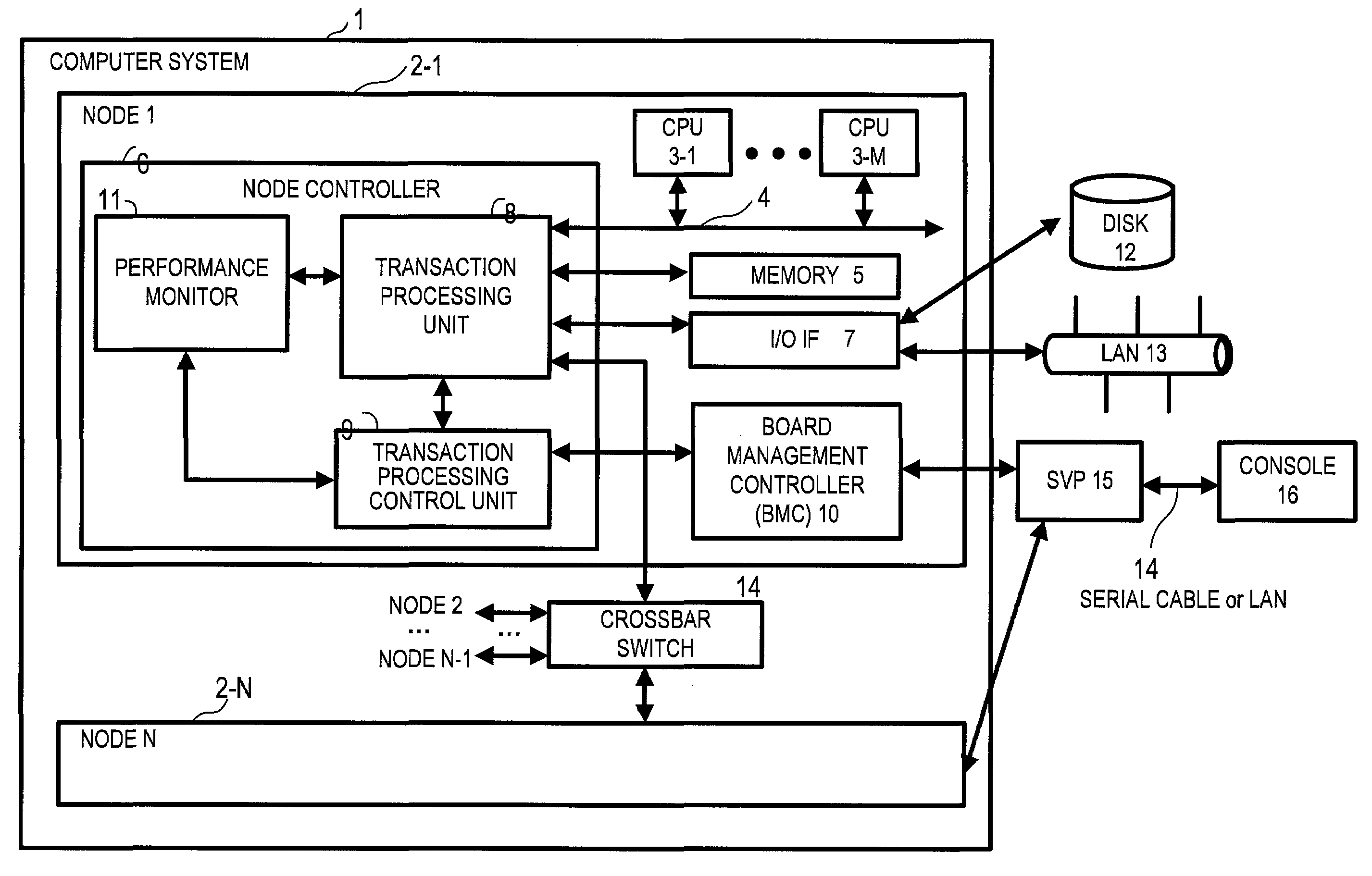
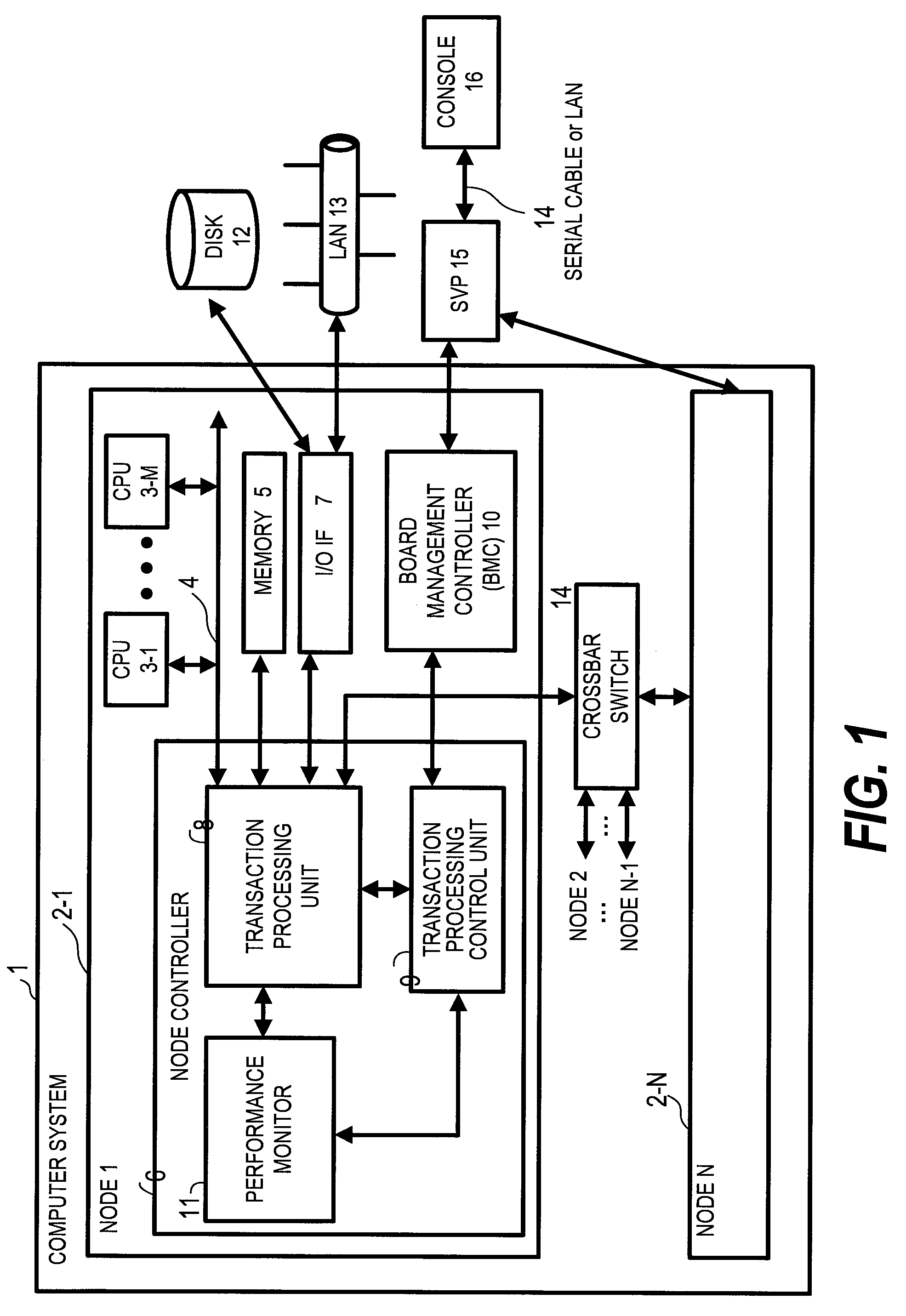
[0193]FIG. 21 shows a second embodiment in which the nodes 2-1 to 2-N of the computer system 1 of the first embodiment are replaced by blade servers 50-1 to 50-N, and a node controller 56 provided in each of the blade servers 50-1 to 50-N measures the performance. The rest of the configuration of the computer system in the second embodiment is the same as in the first embodiment.
[0194]The computer system of the first embodiment is composed of many nodes, and is partitioned physically. Described here is a contrasting example in which a small-scale computer system constitutes the base of the configuration.
[0195]FIG. 21 is a block diagram showing an example of a blade server that is equipped with a hardware monitor of this invention.
[0196]A computer system 1A has multiple blade servers 50-1, 50-2, . . . , 50-N (N is an integer equal to or larger than 1), an I / O board (or I / O blade) 60, and a backplane board 66, which interconnects the blade servers 50-1 to 50-N. The computer system 1A ...
third embodiment
[0239]FIG. 23 shows a third embodiment in which the degree of freedom in the latency measurement performed by the performance monitor 11 shown in FIG. 2 is increased by setting the range and interval of measured latencies arbitrarily.
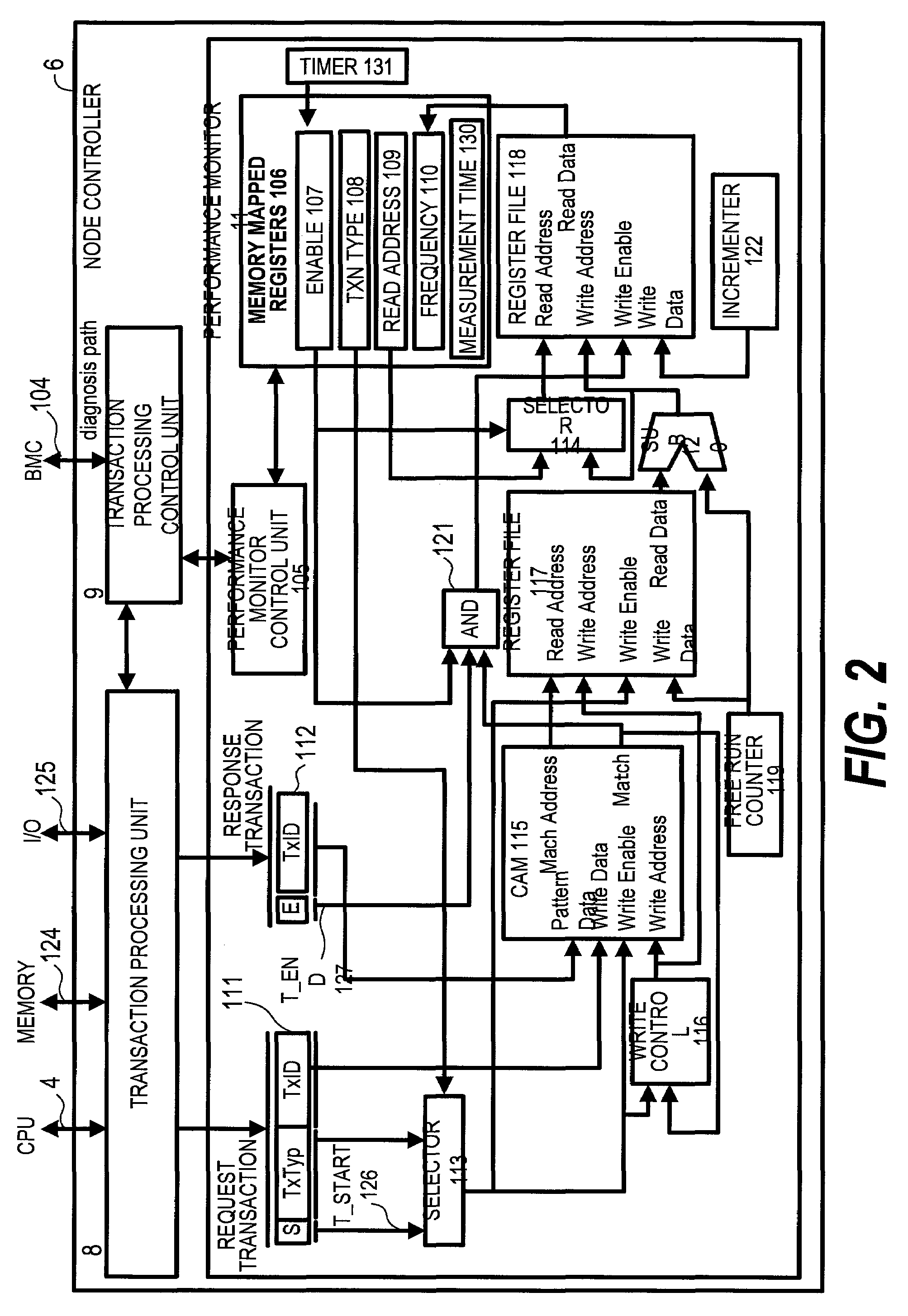
[0240]Adding a circuit shown in FIG. 23 to the performance monitor 11 described in the first embodiment with reference to FIG. 2 makes it possible to set the range and interval of measured latencies and enhance the degree of freedom in the latency measurement. FIG. 23 shows only a part of the performance monitor 11 where the register file 117, the register file 118, and the components in between are located. The rest of the configuration shown in FIG. 23 is the same as the one described in the first embodiment with reference to FIG. 2. Also, components common to FIG. 2 which illustrates the first embodiment are denoted by the same reference symbols.
[0241](1) Circuit Outline
[0242]The outline of the circuit shown in FIG. 23 will be described. Read data of...
PUM
 Abstract
Description
Claims
Application Information
 - R&D
- Intellectual Property
- Life Sciences
- Materials
- Tech Scout
- Unparalleled Data Quality
- Higher Quality Content
- 60% Fewer Hallucinations
Browse by: Latest US Patents, China's latest patents, Technical Efficacy Thesaurus, Application Domain, Technology Topic, Popular Technical Reports.
© 2025 PatSnap. All rights reserved.Legal|Privacy policy|Modern Slavery Act Transparency Statement|Sitemap|About US| Contact US: help@patsnap.com


