Heat exchanger

a technology of heat exchanger and header, which is applied in the direction of steam/vapor condensers, lighting and heating apparatus, and stationary conduit assemblies, etc., can solve the problems of increasing the ability of the header to withstand internal pressure and low production costs

Inactive Publication Date: 2009-08-25
BEHR GMBH & CO KG
View PDF19 Cites 7 Cited by
  • Summary
  • Abstract
  • Description
  • Claims
  • Application Information

AI Technical Summary

Benefits of technology

[0011]According to a further advantageous configuration of the invention, there are three or more longitudinal chambers having two or more longitudinal partitions, with the longitudinal partitions being formed analogously to the individual longitudinal partition described above. This allows the header according to the invention to be used even for relatively large depths of flat tube without the longitudinal passages adopting an excessively large diameter. This gives advantages in terms of installation space and the strength of the header.

Problems solved by technology

This leads to low production costs.
Furthermore, the stamping of the metal sheet produces cold work-hardening, which increases the ability of the header to withstand internal pressure.

Method used


Image

  • Heat exchanger
  • Heat exchanger
  • Heat exchanger

Examples


Embodiment Construction

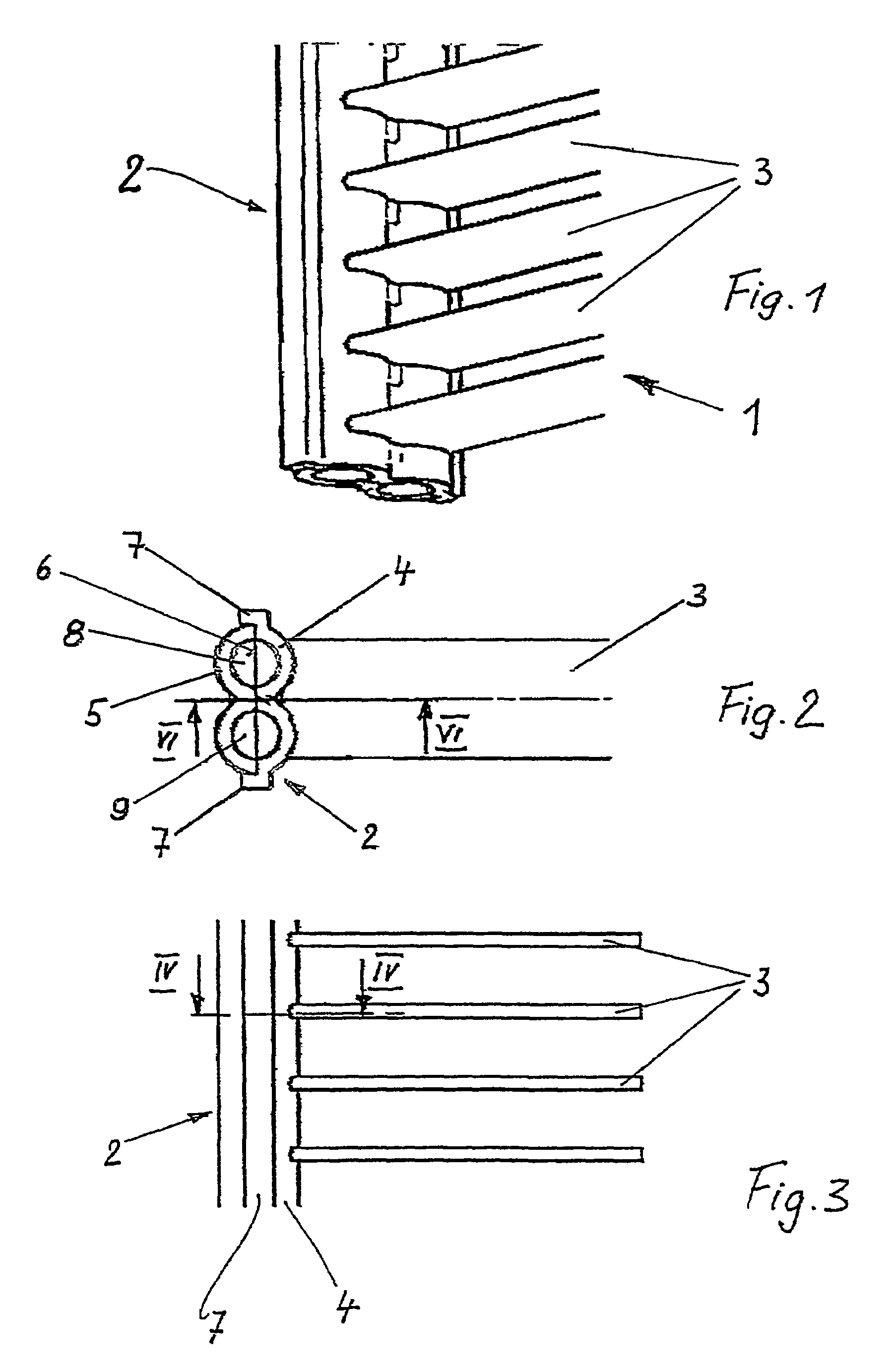
[0029]FIG. 1 shows a heat exchanger which is designed as a gas cooler 1 and has a header 2 and flat tubes 3 which open out into the header and between which corrugation fins (not shown) may be arranged. A gas cooler of this type is used in refrigerant circuits for motor vehicle air-conditioning systems operated with CO2 as refrigerant, but can also be used in general as a pressure-resistant heat exchanger.

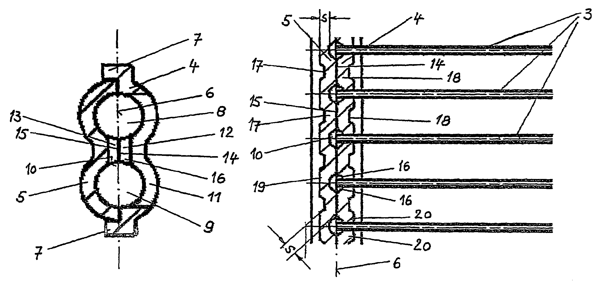
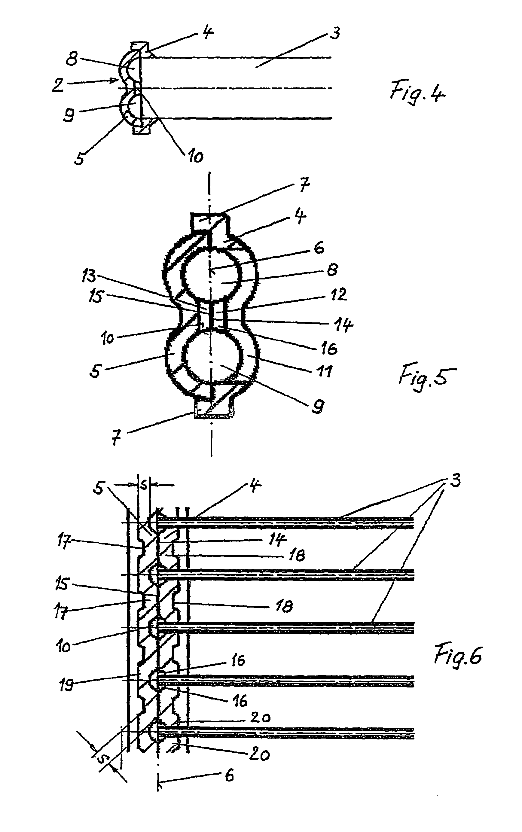
[0030]FIG. 2 shows a side view of the gas cooler 1 with the header 2 which is composed of a tube plate 4 and a cover 5. The tube plate 4 and cover 5 are approximately W-shaped and formed and arranged symmetrically with respect to a parting plane 6, with the tube plate 4 having edge strips 7 which engage laterally around and fix the cover 5. Tube plate 4 and cover 5 form two longitudinal passages 8, 9, which are both substantially circular in cross section. According to another embodiment, the two longitudinal passage have different cross sections. The flat tubes 3 are received by t...


PUM


Abstract

The invention relates to a heat exchanger, especially a gas cooler for CO2, embodied as a cooling agent. The heat exchanger comprises at least one two-part collector unit made of a base and a cover. Said collector unit consists of flat pipes and at least two longitudinal channels with an essentially circular cross-section. The ends of the flat pipes and the base comprise openings for receiving the ends of the pipes. The base, cover and flat pipes are soldered together.

Description

BACKGROUND OF THE INVENTION [0001]The invention relates to a heat exchanger.[0002]Heat exchangers for air-conditioning systems using R134a as refrigerant comprise a heat exchanger network made up of flat tubes and corrugation fins, as well as collection tubes which are arranged on both sides of the network and are preferably circular in cross section, as are known from DE-A 42 38 853 in the name of the present Applicant. Designs of this type have a sufficient strength to cope with the pressures which occur in a condenser. However, with more recent refrigerants, such as CO2, the pressures are considerably higher and the conventional designs of heat exchangers are no longer able to cope with such pressures. Therefore, in the extruded collection tube of increased wall thickness disclosed by WO 98 / 51983, it has been proposed that a collection tube comprise four flow passages of circular cross section arranged next to one another. An extruded collection tube of this type is expensive to ...

Claims


Application Information

Patent Timeline
Patent Type & Authority Patents(United States)
IPC IPC(8): F28F9/02F28D1/02F28D1/053
CPCF28D1/05366F28F9/0224F28F9/0214F28D2021/0073F28F2275/04
Inventor FORSTER, UWEMOLT, KURT
Owner BEHR GMBH & CO KG
Why Eureka
Try Eureka