
Link of conveyor chain

a conveyor chain and chain link technology, applied in the direction of conveyor parts, conveyors, packaging, etc., can solve the problems of high cost of operation, high wear of intermediate supports, and high complexity of production, and achieve the effect of low wear of conveyor chains

Inactive Publication Date: 2009-08-25
HABASIT AG
View PDF14 Cites 9 Cited by
  • Summary
  • Abstract
  • Description
  • Claims
  • Application Information

AI Technical Summary

Benefits of technology

The present invention provides a conveyor chain device that can be used to convey heavy materials or very long shafts without causing wear and tear on the chain. The device is easy to clean, allows for optimal placement of products with narrow resting bases, and is structurally simple and cost-effective. It includes a link with a main base body and two shoulder-like elements, with rollers and supporting elements that help distribute the load evenly. The device also includes a third shaft with rollers that are supported by a separate pair of supporting elements. Overall, the invention solves problems associated with wear and tear, improves cleaning, and optimizes product placement.

Problems solved by technology

One particularly strongly felt need is to allow the products to stop in the chosen positions without requiring the simultaneous stopping of the conveyor chain, which would entail high complexity in production and high costs for its operation.
The main drawback that can be observed in these known types of conveyor chain is that they have high wear of the intermediate supports, since the shaft that rests on them, if turned by the rollers that it supports, slides continuously on said intermediate supports, even in the presence of light loads on the conveyor chain.
Another drawback of known types of conveyor chain is that since each shaft rests directly on the corresponding intermediate support, it is extremely difficult to clean this region of the conveyor chain, and therefore debris from the outside environment or from the conveyed products, such as for example dust or splinters caused by the breakage of glass bottles, can penetrate between the shaft and the intermediate supports, increasing the drag of the chain and accelerating its wear; accordingly, long line downtimes are necessary in order to perform the required cleaning operations.
Another drawback of such known types of conveyor chain is that at the intermediate supports there is a considerable discontinuity in the upper supporting surface, which may give rise to an imperfect placement of the product on the chain, especially when said product has a narrow resting base, consequently hindering the correct execution of the cycle of the system within which said chain is inserted.

Method used


Image

  • Link of conveyor chain
  • Link of conveyor chain
  • Link of conveyor chain

Examples


Embodiment Construction

[0026]In the exemplary embodiments that follow, individual characteristics, given in relation to specific examples, may actually be interchanged with other different characteristics that exist in other exemplary embodiments.

[0027]Moreover, it is noted that anything found to be already known during the patenting process is understood not to be claimed and to be the subject of a disclaimer.

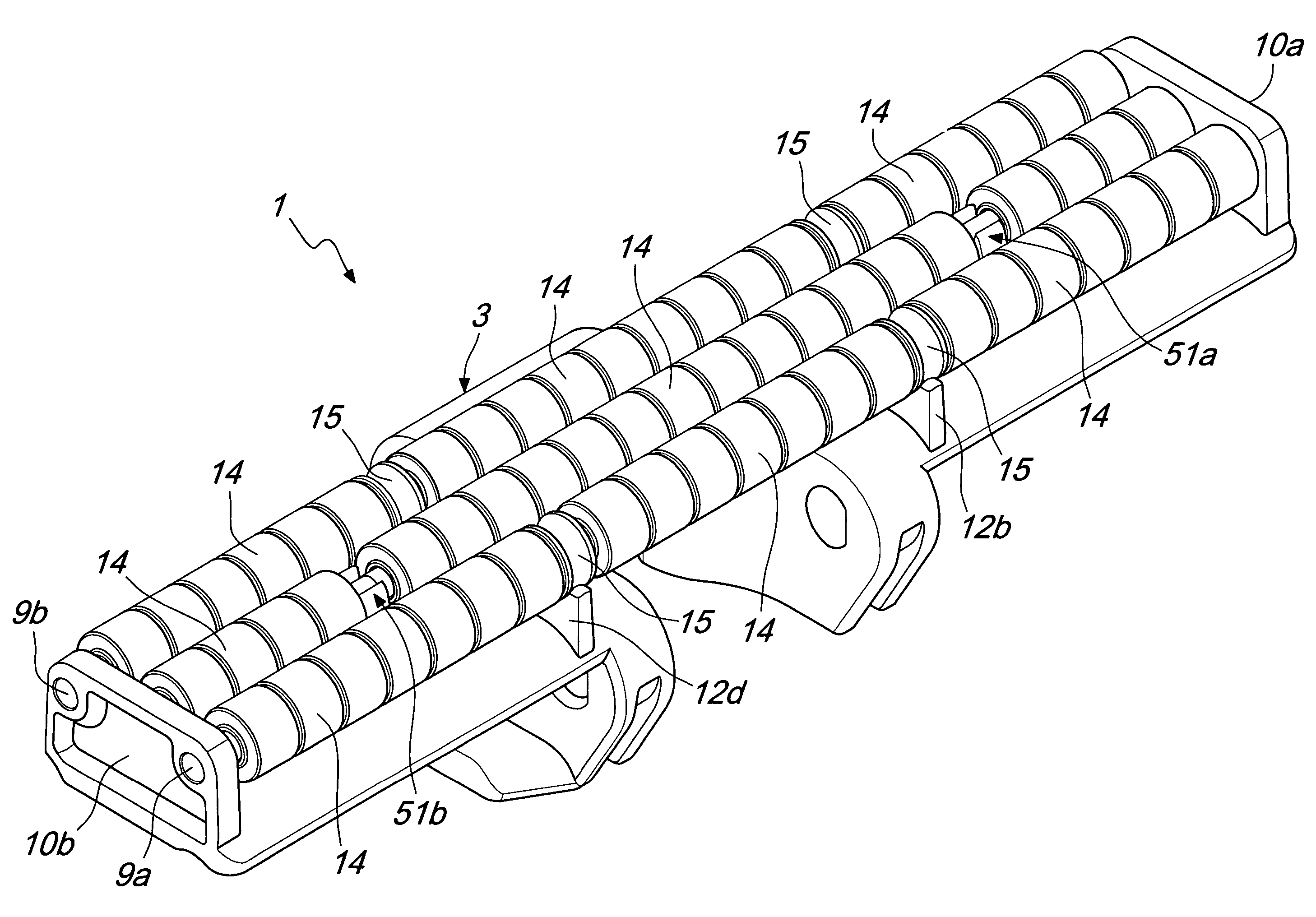
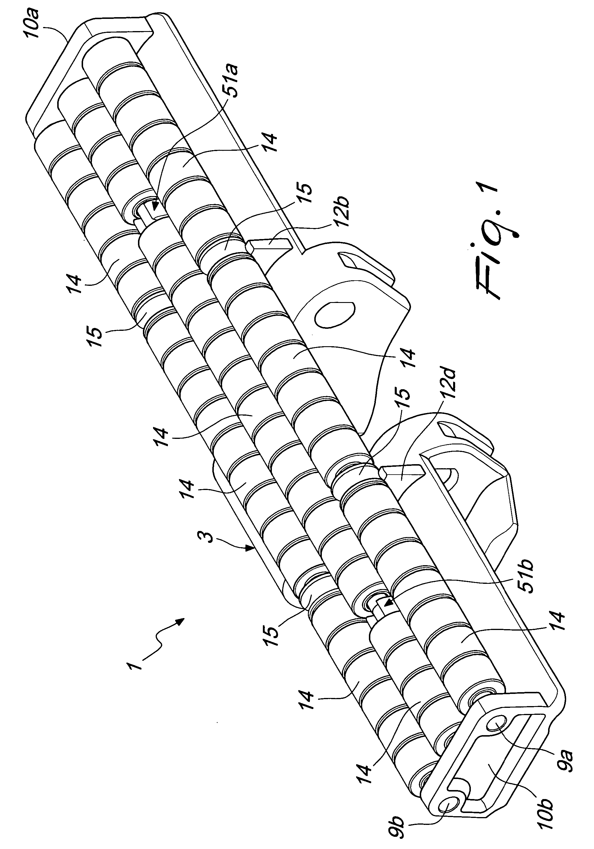
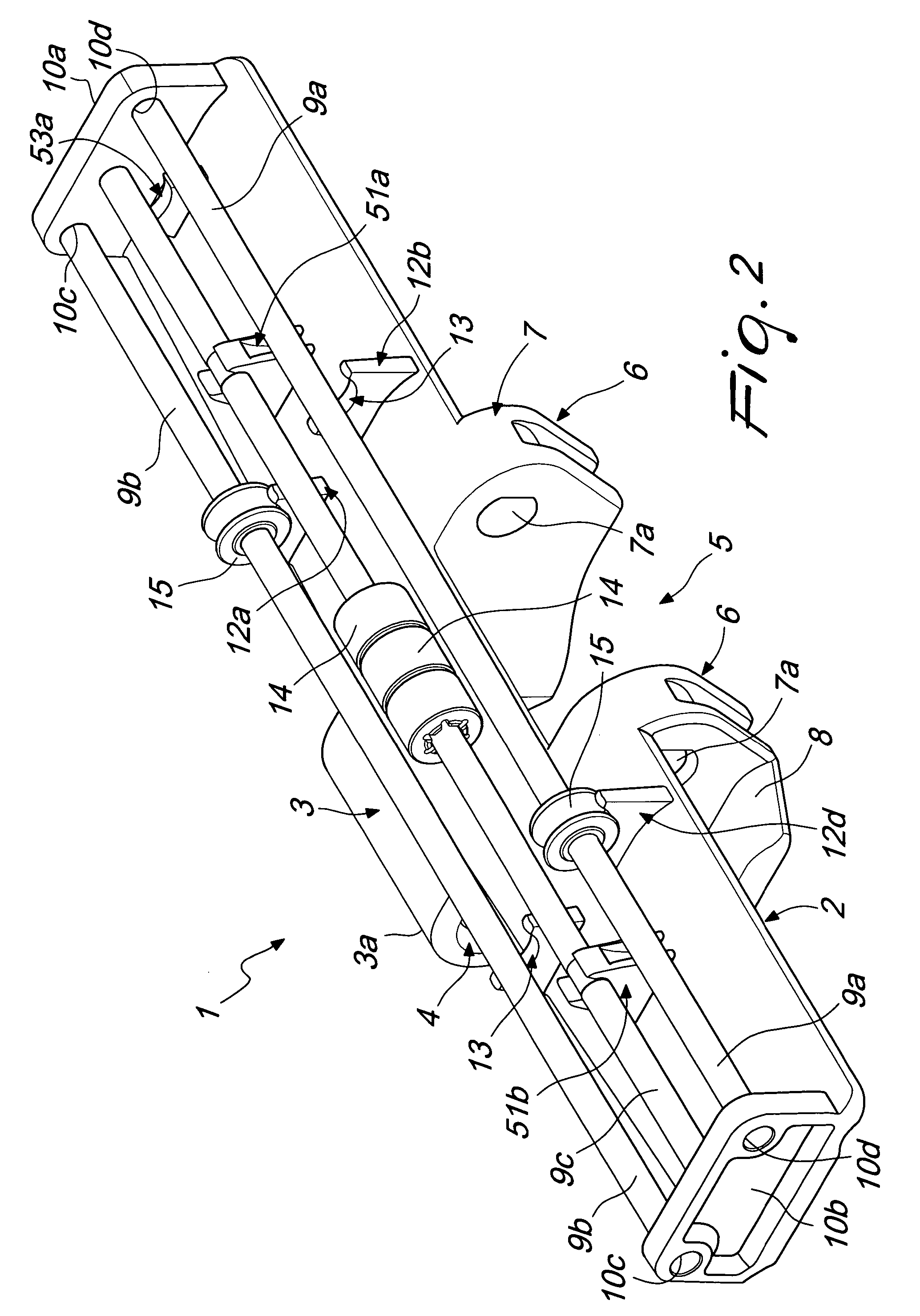
[0028]With reference to the figures, the reference numeral 1 designates a link of a conveyor chain according to the invention, which is constituted by a main base body 2, which is approximately flat and has an approximately rectangular plan shape.

[0029]Two wings 6 can protrude downward from the base body 2, in its central region, and are preferably L-shaped and arranged symmetrically with respect to a central plane of the link 1.

[0030]The link 1 comprises known articulation means for articulated connection to a similar and adjacent link, so as to allow the provision of a conveyor chain which is cons...


PUM


Abstract

A link of a conveyor chain is connectable to a similar and adjacent link and has a main base body with two shoulders, protruding upward from ends of transverse sides of the main base body. Ends of a pair of first and second shafts are associated with the pair of shoulders and first rollers are rotatably associated with the shafts. Second rollers are associated on the pair of first and second shafts and are supported in a loaded condition by at least one pair of first supporting elements, activatable when a load passes. A third shaft, with which third rollers are associated rotatably, is further provided that is supported by at least one pair of second supporting elements, the ends of the third shaft being free.

Description

BACKGROUND OF THE INVENTION[0001]In the provision of industrial systems for bottling liquids or for packaging goods of various kinds, the design of suitable systems for moving the products from one processing station to the next and toward the store is very important.[0002]In performing the production cycles provided by these systems, it is often necessary to convey and stop the conveyed products in chosen positions, so as to be able to perform the various steps provided by said process, such as for example the filling of bottles, their closure, or the packaging of products of various kinds, or the accumulation of packages or containers.[0003]Known types of conveyor chain, composed of a plurality of links which are mutually interconnected so as to form a chosen path, which can comprise straight and curved portions, are currently in use for moving goods within systems in which the working cycles provide for conveying or stopping the products in one or more positions.[0004]One particu...

Claims


Application Information

Patent Timeline
Patent Type & Authority Patents(United States)
IPC IPC(8): B65G17/06
CPCB65G17/08B65G17/32B65G47/261B65G17/40B65G2207/48B65G2201/0244
Inventor FANDELLA, SERGIO
Owner HABASIT AG
Learn More