Delivery system with helical shaft

a delivery system and helical shaft technology, applied in the field of medical devices, can solve the problems of requiring a long recovery time for patients, requiring a long recovery time, and a very invasive procedure for coronary bypass surgery, and achieve the effect of improving the delivery system

Active Publication Date: 2009-08-25
COOK MEDICAL TECH LLC
View PDF10 Cites 30 Cited by
  • Summary
  • Abstract
  • Description
  • Claims
  • Application Information

AI Technical Summary

Problems solved by technology

However, coronary bypass surgery is a very invasive procedure that is risky and requires a long recovery time for the patient.
Generally, separate markers are needed on most intravascular devices since the structure of the device itself usually cannot be seen easily on x-ray or other visualization equipment.
However, at least in the case of stents, current markers may be inadequate when used as pushing members.
This can be a particular problem on longer length stents.
The longer length of some of these stents also makes the stent generally less stable than shorter stents.
As a result, buckling and deformation problems that may occur when pushing on a stent tend to be more pronounced and damaging on longer stents.
However, these types of problems may exist with any stent.
One problem with current delivery systems for intravascular devices is that it can be difficult to precisely release the device within a body cavity.
However, on occasion the physician may encounter difficulties during the intravascular procedure which results in the stent being implanted at a less than optimal location.
This results in greater costs and increased risks due to the extra procedures involved.
In addition, the desirable restenosis of the artery wall that usually encapsulates the stent after implantation may not fully encapsulate the overlapped portion of the stents.
Moreover, when metal stents are used, the overlapping contact between the two stents may corrode and cause an allergic reaction in the patient.
Precise positioning of an intravascular device may be made more difficult for a number of reasons.
One problem that physicians have encountered is a tendency of self-expandable stents and similar devices to “jump” out of the delivery device during release.
Since self-expandable stents are elastic and seek an expanded diameter, the distal end of the stent may rapidly expand in this situation and unexpectedly pull the proximal end of the stent out of the delivery system.
This can make positioning of the stent difficult to control.
The control mechanism may also make precise positioning difficult.
However, the physician may find it difficult to precisely control the movement between the two handles, which may cause the stent or other device to be released in a less than optimal position.
Another problem with conventional delivery systems is that they are usually not adapted to implant more than one intravascular device at a time.
However, in many procedures multiple devices may need to be released within the body cavity being treated.
The disadvantage of this is that each time a delivery system must be introduced and withdrawn damage may occur to the passageways.
The overall length of the procedure and the cost of the procedure is also increased.

Method used


Image

  • Delivery system with helical shaft
  • Delivery system with helical shaft
  • Delivery system with helical shaft

Examples


Embodiment Construction

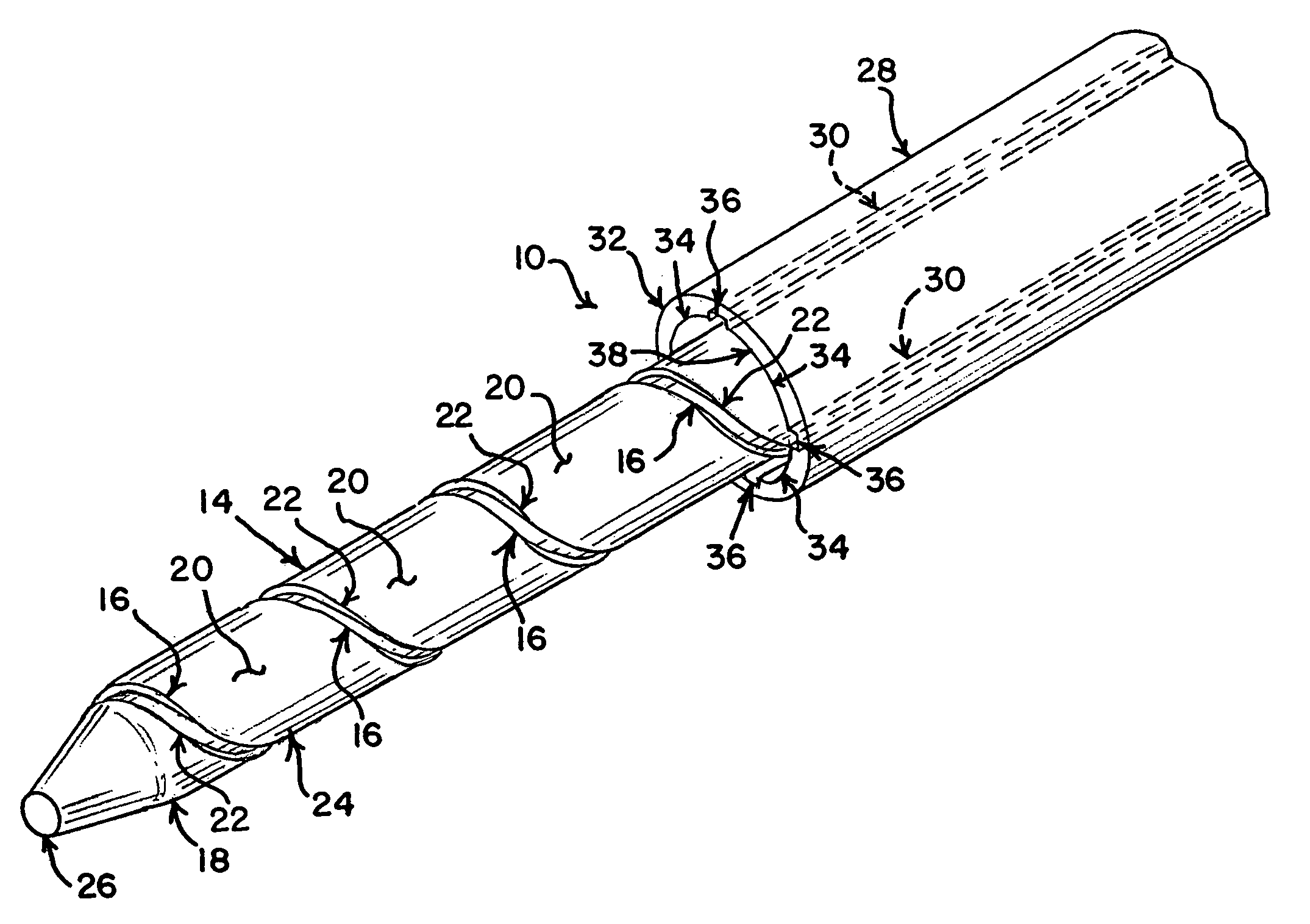
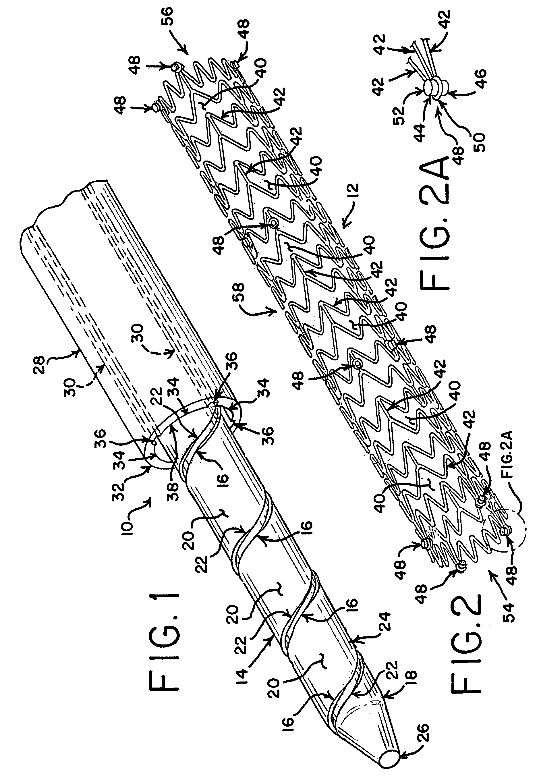
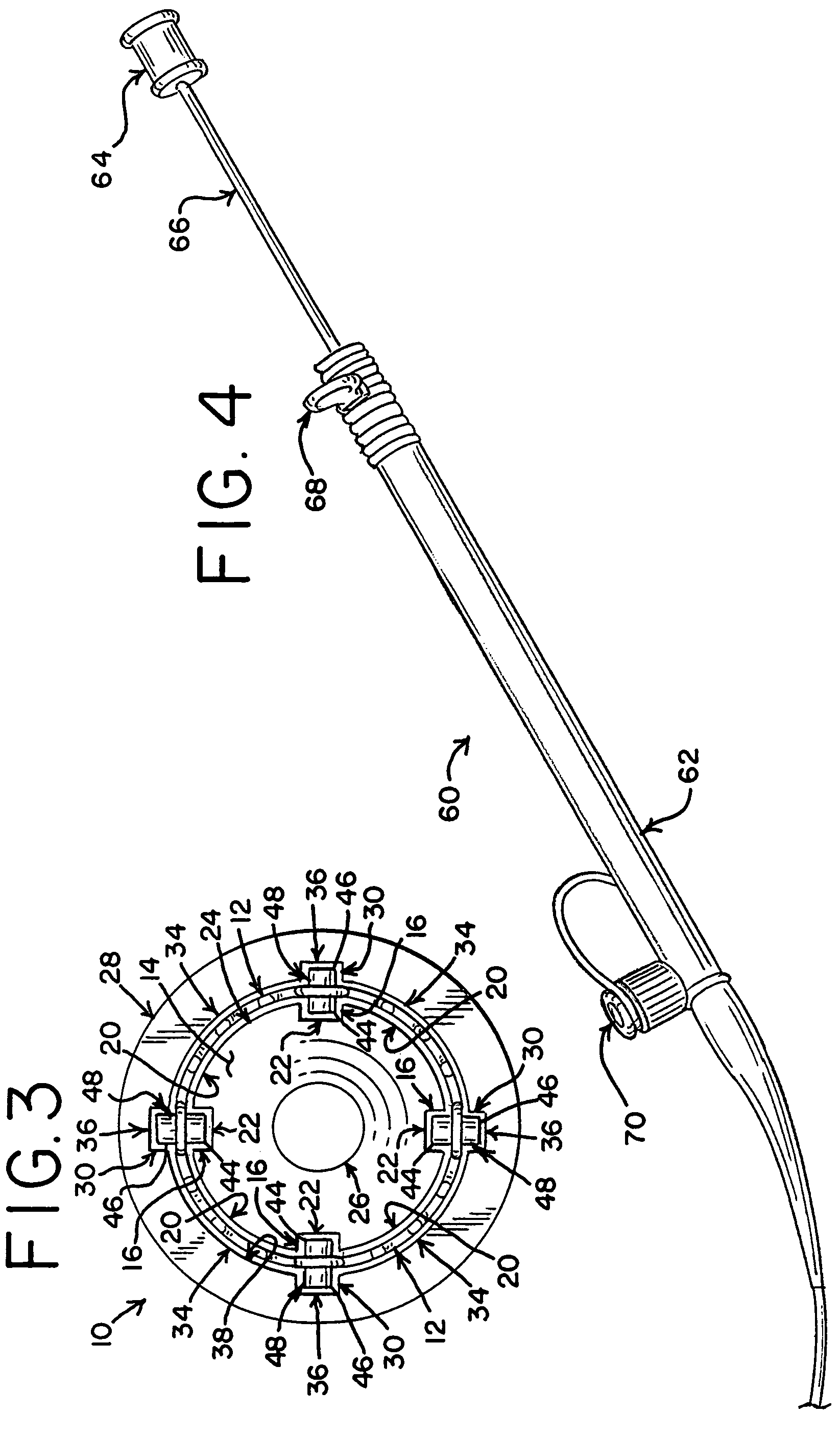
[0023]Referring now to the drawings, a delivery system 10 for medical devices is shown. In particular, the embodiment shown and described is adapted for intravascular delivery of a self-expandable stent 12. However, the structure taught herein may also be adapted for other uses as well.

[0024]As shown in FIG. 1, the delivery system 10 includes a shaft 14, or core, with a helical groove 16 along a portion of the distal end 18 of the shaft 14. The helical groove 16 is defined by a helical raised region 20 and a helical recessed region 22. Thus, the interposition of the helical raised region 20 and the helical recessed region 22 forms a helical groove 16. The helical raised region 20 may form the outer circumference 24 of the shaft 14. A guidewire lumen 26 is provided through the shaft 14 to allow a guidewire to pass axially through the delivery system 10. The delivery system 10 also includes a sheath 28 that surrounds the shaft 14 and may be moved longitudinally relative to the shaft 1...


PUM


Abstract

A delivery system is provided for releasing a medical device within a body cavity. The delivery system may be used in an intravascular procedure to implant a self-expandable stent. A helical structure on the shaft of the delivery system engages the inner surface of the stent. As a result, the stent may be released by rotating the shaft relative to the stent which pushes the stent forward from the distal end of the shaft.

Description

BACKGROUND[0001]The present invention relates generally to medical devices and more particularly to a delivery system in which the medical device is interposed between a shaft and a sheath.[0002]The use of stents to treat various organs, such as the vascular system, colon, biliary tract, urinary tract, esophagus, trachea and the like, has become common in recent years. Stents are useful in a variety of medical procedures and are often used to treat blockages, occlusions, narrowing ailments and other related problems that restrict flow through a passageway. One common medical procedure in which stents are used involves implanting an endovascular stent into the vascular system. Stents have been shown to be useful in treating numerous vessels throughout the vascular system, including coronary arteries, peripheral arteries (e.g., carotid, brachial, renal, iliac and femoral), and other vessels.[0003]Although stents and other medical devices are used in many different procedures, the use ...

Claims


Application Information

Patent Timeline
Patent Type & Authority Patents(United States)
IPC IPC(8): A61F2/84
CPCA61F2/91A61F2/915A61F2/95A61F2230/0054A61F2002/91533A61F2002/91575A61F2002/9665A61F2002/91525
Inventor MELSHEIMER, JEFFRY S.
Owner COOK MEDICAL TECH LLC
Why Eureka
Try Eureka