Optical apparatus with dust reduction capability

a technology of optical apparatus and dust reduction glasses, which is applied in the field of optical apparatuses with dust reduction glasses, can solve the problem of no dust reduction measures for optical apparatuses provided with dust reduction glasses

Inactive Publication Date: 2009-08-25
OLYMPUS CORP
View PDF5 Cites 20 Cited by
  • Summary
  • Abstract
  • Description
  • Claims
  • Application Information

AI Technical Summary

Benefits of technology

[0008]An optical apparatus with dust reduction capability of the present invention includes a plurality of dust reduction optical elements driven to vibrate by a single circuit in a dust removal operation. Since the single circuit drives the dust reduction optical elements, it is effective in providing a compact, low-cost apparatus.
[0010]Further, while the driving frequency is being varied, dust reduction optical elements having resonance frequencies different from the current driving frequency can be set not to vibrate at the driving frequency. This can save energy consumption.
[0012]Further, the vibration of one dust reduction optical element can be propagated to the other dust reduction optical element using sonic wave action to realize dust removal from both optical elements. In this case, if the vibration exciting signal applied to the former optical element contains both the resonance frequency of the optical element and the resonance frequency of the other optical element, the effect can be enhanced.
[0022]Furthermore, the electronic camera can be configured such that the drive circuit has a switching circuit for selectively driving each of the electromechanical conversion elements, and the control circuit controls the operation of the drive circuit to change the driving time depending on the electromechanical conversion element selectively driven. In this case, the dust removal effect can be enhanced by setting proper driving time.

Problems solved by technology

However, there has been proposed no dust reduction measures for optical apparatuses provided with dust reduction glasses at multiple positions.

Method used


Image

  • Optical apparatus with dust reduction capability
  • Optical apparatus with dust reduction capability
  • Optical apparatus with dust reduction capability

Examples


first embodiment

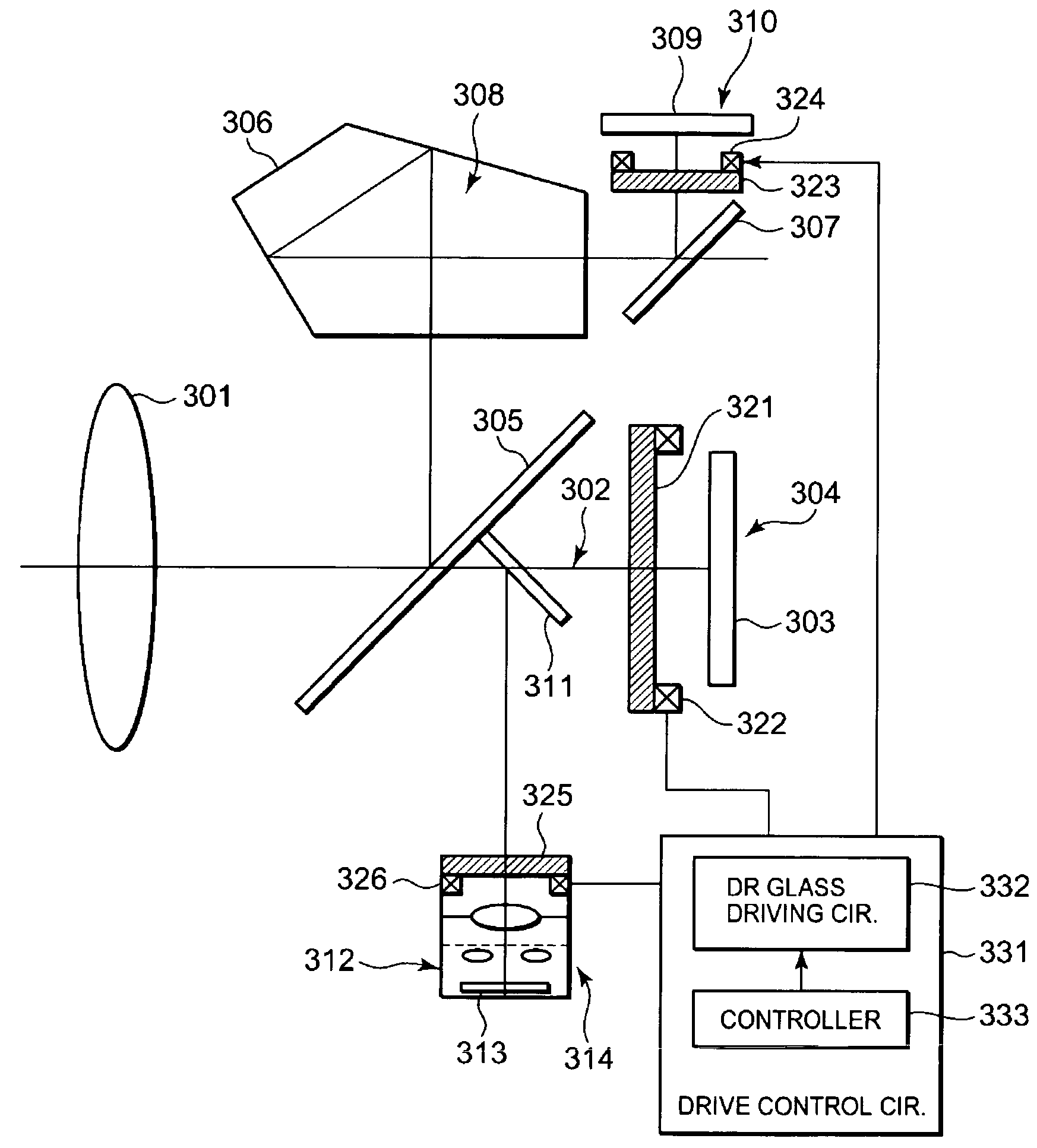
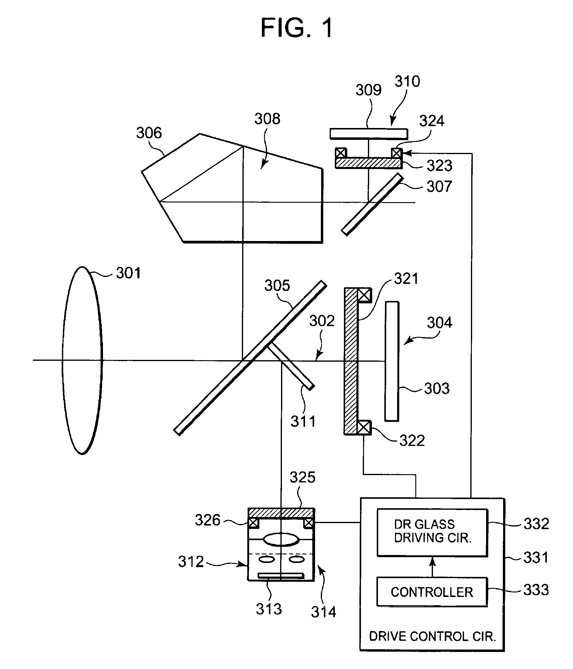
[0065]FIG. 1 is a schematic diagram of a digital camera system as an optical apparatus with dust reduction capability according to a first embodiment of the present invention. FIG. 1 shows the structure of the digital camera with consideration given to an actual optical arrangement.

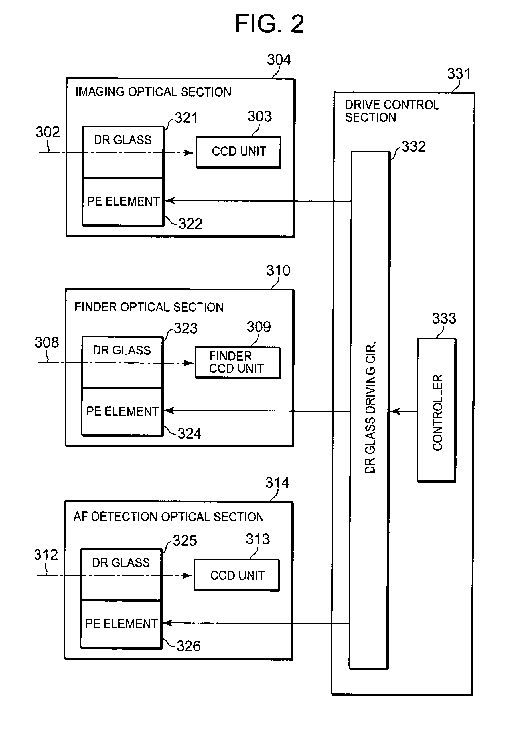
[0066]The optical apparatus with dust reduction capability includes an imaging optical section 304. The imaging optical section 304 has an imaging optical system 302 and a CCD unit 303. The imaging optical system 302 is an image-forming optical system having a taking lens 301 as its main part. The CCD unit 303 is a photoelectric converter, or to be more specific, an imaging photoelectric converter, for receiving an optical subject image formed through the imaging optical system 302 and converting it to an electric signal.

[0067]The optical apparatus with dust reduction capability also includes a finder optical section 310. The finder optical section 310 has a finder optical system 308 and a finder CCD unit...

second embodiment

[0150]The following describes a second embodiment of the present invention. In summary, in the second embodiment, the drive control section 331 selectively drives each of the piezoelectric elements 322, 324, and 326 to vibrate each of the dust reduction glasses 321, 323, and 325 in a time-sharing manner. Particularly, the second embodiment assumes a case where each of the dust reduction glasses 321, 323, and 325 has a different resonance frequency as indicated by fc 321, fc 323, or fc 325, respectively. In operation, the drive control section 331 selectively drives each of the piezoelectric elements 322, 324, and 326 to scan a predetermined frequency range including the resonance frequency of each of the dust reduction glasses 321, 323, and 325 so as to vibrate each of the dust reduction glasses 321, 323, and 325 in a time-sharing manner. For example, the driving frequency is so changed that the dust reduction glass 321 will be driven only for a period during which the driving frequ...

third embodiment

[0157]The following describes a third embodiment of the present invention. The description of the third embodiment focuses on the point that the vibration exciting element is the piezoelectric element. In summary, each of the piezoelectric elements 322, 324, and 326 is applied with a voltage varying from element to element. In other words, the applied voltage is used as an optimum parameter for each of the piezoelectric elements 322, 324, and 326 to vibrate each of the dust reduction glasses 321, 323, and 325, so that the applied voltage is switched to vibrate each of the dust reduction glass 321, 323, and 325 for dust reduction operation.

[0158]As mentioned above, since the piezoelectric element 322, 324, 326 are different in size, shape, and usage, they are different in dust removal performance required, that is, in the amplitude of vibration. One of methods for adjusting the amplitude is a method of changing the applied voltage to each piezoelectric element. FIG. 18 is a graph sho...


PUM


Abstract

The present invention realizes efficient dust removal in an optical apparatus in such a manner that a single circuit drives a plurality of dust reduction optical elements to vibrate. When the optical elements have different resonance frequencies, it can be configured such that the vibration exciting frequency can be changed in a range including the resonance frequencies of all the optical elements. In this case, the optical element driven can also be switched according to the change in frequency so that only the optical element having a resonance frequency close to the driving frequency will be driven. Alternatively, it can be configured such that the driving time or applied voltage can be changed according to the characteristics of the optical element driven.

Description

CROSS-REFERENCE TO RELATED APPLICATION[0001]This application is based upon and claims the benefit of priority from prior Japanese Patent Application No. 2005-075865, filed on Mar. 16, 2005, the entire contents of which are incorporated herein by reference.BACKGROUND OF THE INVENTION[0002]1. Field of the Invention[0003]The present invention relates to an optical apparatus with dust reduction capability of removing dust adhering to the inside of the apparatus. For example, as such an optical apparatus with dust reduction capability, there is an electronic imaging apparatus such as a digital camera system provided with a dust reduction function.[0004]2. Description of the Related Art[0005]A technique for removing dust adhering to a cover glass for protecting an image pickup device of an optical apparatus by vibrating the cover glass has been recently proposed as an example of dust reduction technology for optical apparatuses. For example, Japanese Patent Laid-Open No. 2004-48665 disclo...

Claims


Application Information

Patent Timeline
Patent Type & Authority Patents(United States)
IPC IPC(8): G03B17/00
CPCG02B27/0006G03B17/02H04N23/52H04N23/811
Inventor IDE, MASATAKAITO, JUNICHI
Owner OLYMPUS CORP
Why Eureka
Try Eureka