Protector

a protection device and shielding technology, applied in the field of protection devices, can solve the problems of low versatility and increase the cost, and achieve the effects of improving versatility, convenient positioning, and convenient mounting

Inactive Publication Date: 2009-09-01
SUMITOMO WIRING SYST LTD
View PDF11 Cites 53 Cited by
  • Summary
  • Abstract
  • Description
  • Claims
  • Application Information

AI Technical Summary

Benefits of technology

[0013]The corrugated tube can be mounted between the pair of temporary fitting ribs to prevent lateral displacement of the corrugated tube. Longitudinal displacement of the corrugated tube also is prevented by inserting the temporary fitting ribs into the groove. Upward movements of the corrugated tube from the member are prevented by the stand-up ends bent to approach each other. Thus, the corrugated tube need not be pressed by the hand to prevent displacements relative to the half member, and hence the efficiency of the mounting operation of the protector can be improved.
[0049]The front surface of the projection in the inserting direction of the engaging part may be formed into a riding surface inclined so that the projecting distance of the projection gradually increases toward the back side in the inserting direction. Thus, the bulging plate moves onto the riding surface without getting caught by the projection and is inserted smoothly into the accommodating portion. As a result, the engaging part can be mounted easily.

Problems solved by technology

The need to press the main-line corrugated tube and the branch-line corrugated tube by hand to prevent displacements takes time and labor and therefore is inefficient.
Thus, if corrugate tubes differ in diameter, protectors sized in conformity with the different diameters must be prepared, leading to increased cost.
Accordingly, a wire laying direction is determined upon mounting the protector on the body panel, and many types of protectors have to be prepared to lay bundles of wires in specified directions, thereby presenting a problem of low versatility.

Method used


Image

  • Protector
  • Protector
  • Protector

Examples


first embodiment

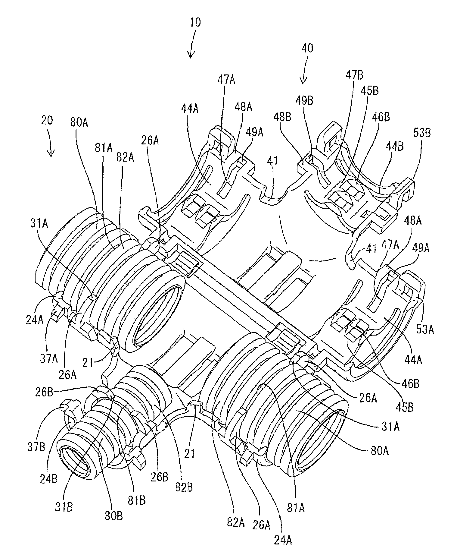
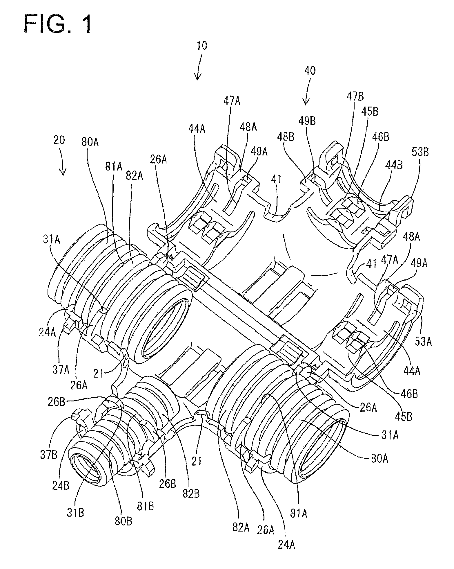
[0172]The temporary fixing ribs 26A, 26B are continuous with the first peripheral wall 22 via the supporting shafts 36A, 36B in the first embodiment and are displaceable inward and outward about the axial lines of the supporting shafts 36A, 36B. However, they may be continuous with the first peripheral wall 22 without the supporting shafts and may not be displaceable.

[0173]Two temporary fixing ribs 26A, 26B are provided on each of the main-line tube holders 13 and branch-line tube holder 14 in the first embodiment. However, they need not be provided on each tube holder.

[0174]The second peripheral wall 42 is formed with the windows 47A, 47B for permitting the penetration of the temporary fixing ribs 26A, 26B in the first embodiment. However, the windows may not necessarily be formed or may extend from the second peripheral wall to the first peripheral wall.

[0175]The second half member 40 is provided with the deformation restricting portions 48A, 48B for preventing displacements of th...

third embodiment

[0197]Although the leg 231 includes the first and second projections 237A and 237B in the third embodiment, they may be omitted. Alternatively, only the first or second projections may be provided.

[0198]Although two first and second projections 237A and 237B are provided, only one of each of the first and second projections may be provided.

[0199]The mounting portion 71 is aligned so that the engaging part 230 is inserted parallel to the branching direction of the branch 12 in the third embodiment, but it may be aligned in any direction.

[0200]The outer surfaces of the resilient plate 249 and the branch 12 are substantially flush with each other, but they need not be flush with each other.

[0201]The slanted surfaces 243 for the engaging leg are formed at the open end of the mount groove 241 for the leg 231, but need not be formed.

[0202]The surrounding-wall slanted surfaces 246 and the guide-plate slanted surfaces 247 are formed at the open end of the accommodating space 245, but either...


PUM

PropertyMeasurementUnit
resilientaaaaaaaaaa
thicknessaaaaaaaaaa
heightaaaaaaaaaa

Abstract

A protector (10) has two half members (20, 40) forming a tubular shape upon being assembled. One half member (20) includes a pair of temporary fixing ribs (26A, 26B) projecting more than a contact edge (23) with the other half member (40) and standing up at the opposite sides of each of corrugated tubes (80A, 80B), each pair of temporary fixing ribs (26A, 26B) are shaped to be insertable into grooves (81A, 81B) of the corresponding corrugated tube (80A, 80B), and stand-up ends (27A, 27B) of the pair of temporary fixing ribs (26A, 26B) are bent to approach each other along the groove (81A, 81B) of the corrugated tube (80A, 80B).

Description

BACKGROUND OF THE INVENTION[0001]1. Field of the Invention[0002]The invention relates to a protector for holding a corrugated tube.[0003]2. Description of the Related Art[0004]Japanese Unexamined Patent Publication No. H09-294320 discloses a protector for protecting corrugated tubes. The protector is mounted on a branched part of a bundle of wires and is substantially T-shaped with a main line portion covering a main-line of the wires and a branch covering a branch line of the wires. The protector has first and second half members connected by a hinge and is mounted while holding the corrugated tubes covering the wires between the half members. The corrugated tubes are held to project from ends of the protector while covering the wires. Thus, the wires are not damaged by contact with the end edges of the protector.[0005]The half members first are held in an open state for mounting the protector. The first half member then is placed on the main-line corrugated tube that is mounted on...

Claims


Application Information

Patent Timeline
Patent Type & Authority Patents(United States)
IPC IPC(8): F16L21/00
CPCF16L21/06F16L25/0045F16L41/021F16L47/32F16L57/00Y10S285/921Y10S285/903H02G3/06H02G3/0468H02G3/0691
Inventor TANAKA, NOBUYOSHIIBARAKI, MASATOSAKATA, TSUTOMUMORII, TOSHITSUGU
Owner SUMITOMO WIRING SYST LTD
Why Eureka
Try Eureka