Gantry for medical particle therapy facility

a gantry and medical particle technology, applied in the field of medical particle delivery systems, can solve the problems of inability to meet the needs of patients, etc., and achieve the effect of improving the gantry design of typical cancer therapy facilities

Active Publication Date: 2009-09-01
BROOKHAVEN SCI ASSOCS
View PDF4 Cites 56 Cited by
  • Summary
  • Abstract
  • Description
  • Claims
  • Application Information

AI Technical Summary

Problems solved by technology

Because of these requirements, the gantry of a conventional particle beam cancer therapy facility is typically the most expensive piece of equipment of the treatment facility and its magnets are generally very large and heavy.
Such advances, however, have heretofore not been applied to the gantry design of typical cancer therapy facilities.

Method used


Image

  • Gantry for medical particle therapy facility
  • Gantry for medical particle therapy facility
  • Gantry for medical particle therapy facility

Examples


Embodiment Construction

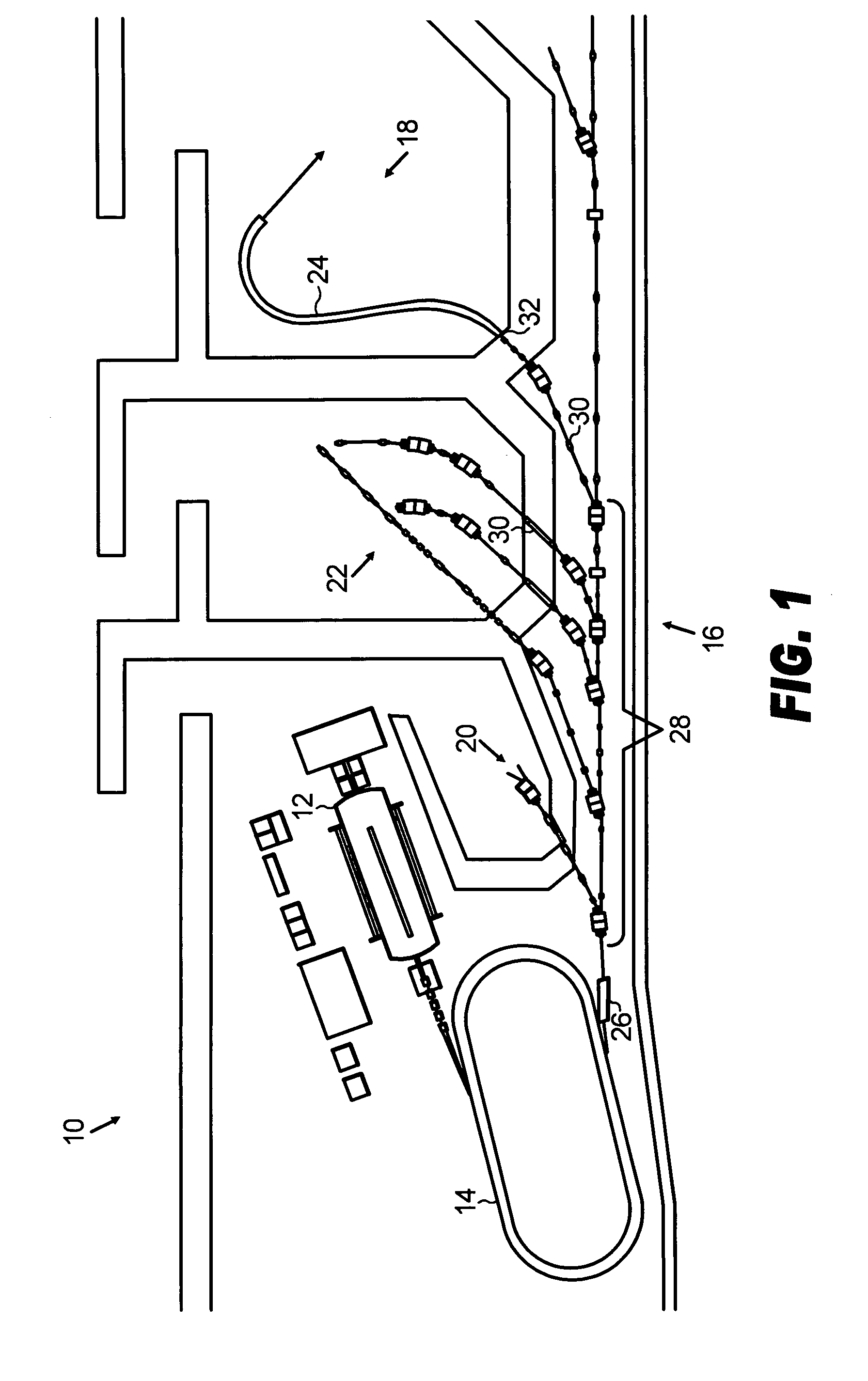
[0030]FIG. 1 shows a typical medical particle delivery therapy facility 10. The facility 10 generally includes an injector 12, a particle accelerator 14, and a beam delivery network 16 including a rotatable gantry treatment room 18 for delivering a beam to a patient. The beam delivery network 16 may also be designed to divert independent beams to various other applications as desired. For example, the beam delivery network 16 may be designed to deliver a beam to a beam research room 20 and a fixed beam treatment room 22. The research room 20 may be provided for research and calibration purposes, with an entrance separate from the patient areas, while the fixed beam treatment room 22 may include separate beam lines for such therapeutic applications, such as eye treatments.

[0031]The beam injector module 12 can be a conventional LINAC or a tandem Van de Graaf injector with an injection kicker, which completes the task of particle injection into the accelerator 14. In the case of proton...


PUM


Abstract

A particle therapy gantry for delivering a particle beam to a patient includes a beam tube having a curvature defining a particle beam path and a plurality of fixed field magnets sequentially arranged along the beam tube for guiding the particle beam along the particle path. In a method for delivering a particle beam to a patient through a gantry, a particle beam is guided by a plurality of fixed field magnets sequentially arranged along a beam tube of the gantry and the beam is alternately focused and defocused with alternately arranged combined function focusing and defocusing fixed field magnets.

Description

BACKGROUND OF THE INVENTION[0001]The present invention relates generally to a medical cancer therapy facility and, more particularly, to a medical particle delivery system having a compact gantry design.[0002]It has been known in the art to use a particle accelerator, such as a synchrotron, and a gantry arrangement to deliver a beam of particles, such as protons, from a single source to one of a plurality of patient treatment stations for cancer therapy. In such systems, the cancerous tumor will be hit and destroyed by particles in a precise way with a localized energy deposition. Thus, the number of ion interactions on the way to the tumor through the healthy body cells is dramatically smaller than by any other radiation method. A position of the center of the tumor inside the body defines a value of the particle energy. The transverse beam raster is defined by the transverse size of the tumor with respect to the beam, while the width of the tumor defines the beam energy range. The...

Claims


Application Information

Patent Timeline
Patent Type & Authority Patents(United States)
IPC IPC(8): G21G1/10
CPCA61N5/10A61N5/1079H05H7/04G21K1/093A61N5/1081A61N2005/1087
Inventor TRBOJEVIC, DEJAN
Owner BROOKHAVEN SCI ASSOCS
Why Eureka
Try Eureka