Control unit for yarn-braking devices in weft feeders for looms, and tuning method therefor

a technology of weft feeder and control unit, which is applied in the direction of weaving, looms, instruments, etc., can solve the problems of large reduction of accuracy and compensation error, and achieve the effect of short execution time and easy automation

Inactive Publication Date: 2009-09-01
L G L ELECTRONICS
View PDF9 Cites 12 Cited by
  • Summary
  • Abstract
  • Description
  • Claims
  • Application Information

AI Technical Summary

Benefits of technology

[0005]Therefore, it is a main object of the present invention to provide a control unit for yarn-braking devices in weft feeders for looms, which can be tuned in an automatized way on the basis of variable parameters concerning the yarn-braking device, in particular, the stiffness of the springs and the static pressure, as well as to provide a setting or tuning method for the control unit, which can be easily automatized and requires a short execution time.

Problems solved by technology

Although the above control unit allows the braking action to be modulated smoothly and dynamically, however it has the drawback that its accuracy considerably decreases when certain parameters are changed, such as the stiffness of the springs which support the frustoconical member, or the static pressure applied upon the drum by the cone, which parameters are chosen, e.g., on the basis of the type of yarn under processing, the loom speed, the loom height, and the like.
On the contrary, changing these parameters results in an error of compensation.

Method used


Image

  • Control unit for yarn-braking devices in weft feeders for looms, and tuning method therefor
  • Control unit for yarn-braking devices in weft feeders for looms, and tuning method therefor
  • Control unit for yarn-braking devices in weft feeders for looms, and tuning method therefor

Examples


Embodiment Construction

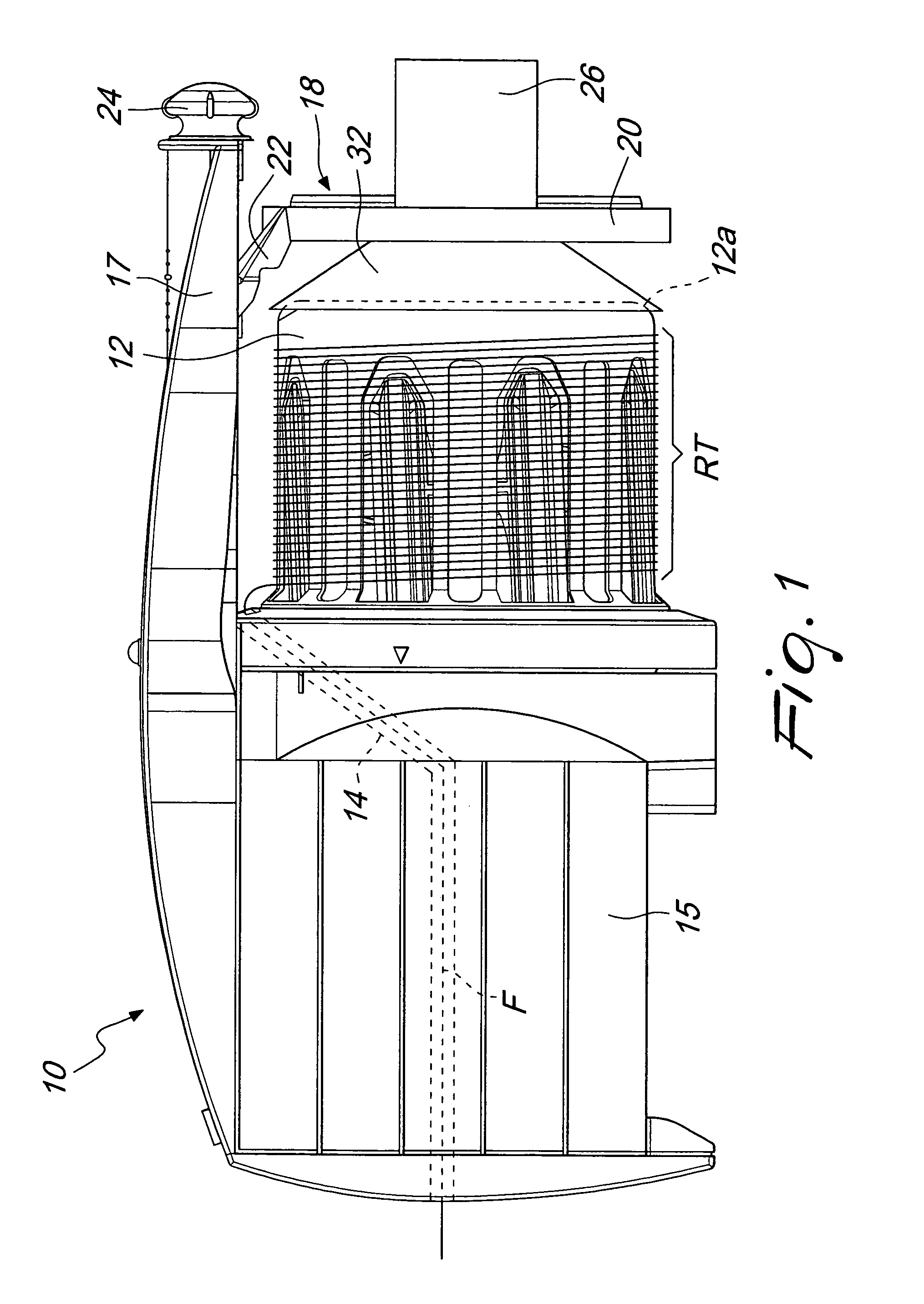
[0014]With reference to the above Figures, a weft feeder 10 for textile machines comprises a stationary drum 12 provided with a beveled delivery edge 12a, on which a swivel arm 14 driven by a motor 15 winds a plurality of yarn loops forming a weft reserve RT.

[0015]A stationary arm 17 parallel to the axis of the drum projects from the motor housing and supports a yarn-braking device 18 having the task of controlling the tension of the yarn unwinding from the drum.

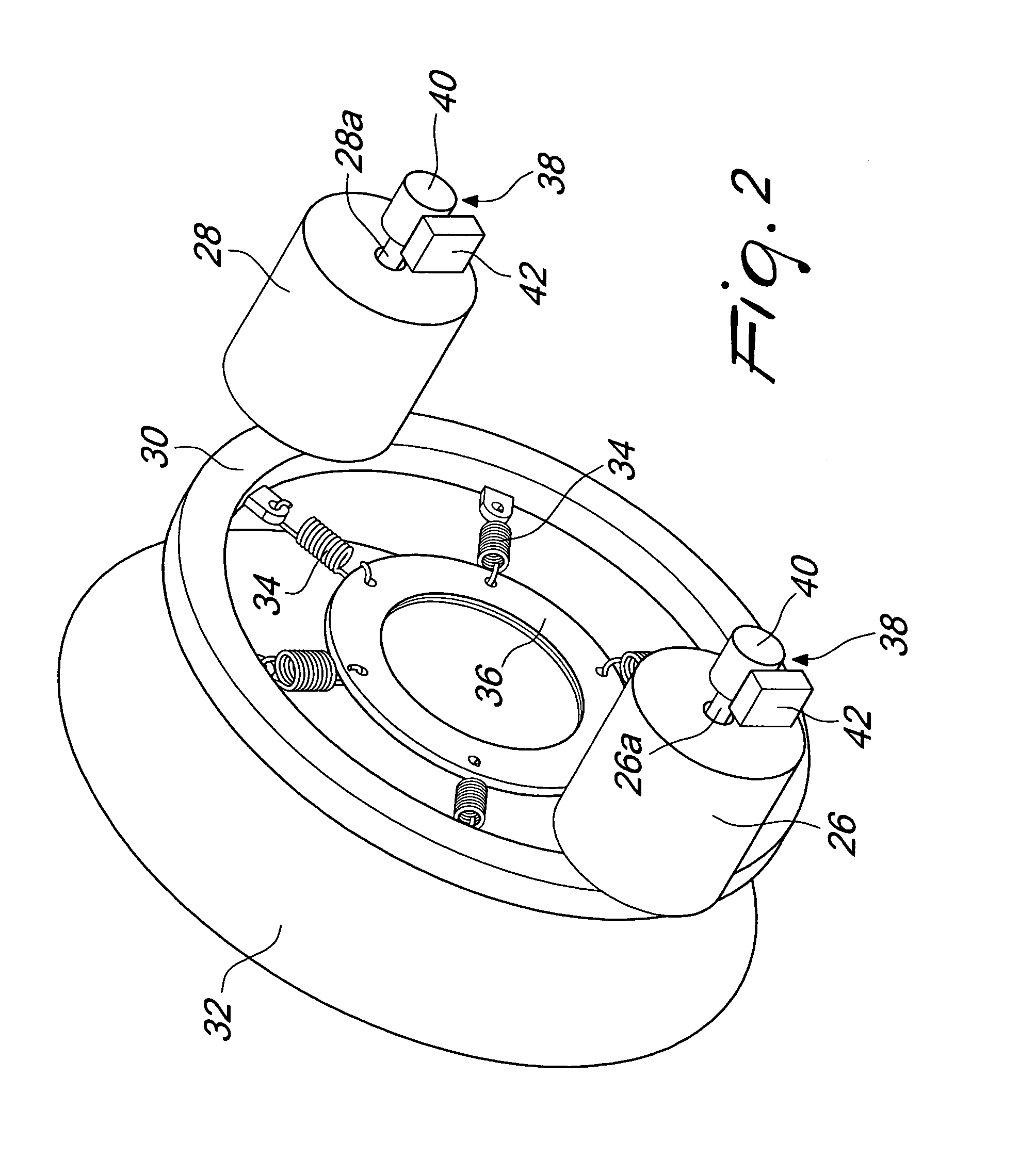
[0016]The yarn-braking device 18 comprises a frame 20 supported on a slide 22 that is movable along the stationary arm 17 under control of a worm screw mechanism (not shown) that is operable by a knob 24. In a known way, frame 20 supports a pair of electromechanical, linear actuators 26, 28 (FIG. 2) arranged with their respective driving rods 26a, 28a parallel to the axis of the drum at respective, diametrically opposed positions. An annular support 30 coaxial with the drum is supported at the free ends of the driving rods. ...


PUM


Abstract

A control unit for yarn-braking devices in weft feeders for looms, in which the yarn unwinding from the feeder is pressed between a drum and a braking member connected to two linear actuators controlled by position and provided with position sensors. A position control loop receives a position signal from the sensor and compares it with a reference variable in a subtracter for obtaining a position error. A position compensator receives the position error and outputs a reference current entering a current control loop connected to generate a voltage that supplies the actuator. The compensator incorporates a control transfer function that is variable as a function of an elastic constant of a mass-spring equivalent system, where the mass is the mass of the parts in motion between the braking member and the actuators, and the elastic constant matches with the elastic constant of the elastic elements.

Description

[0001]The present invention relates to a control unit for yarn-braking devices in weft feeders for looms, in particular rapier looms, projectile looms and air-jet looms, and to a tuning method therefor.BACKGROUND OF THE INVENTION[0002]As it is known, weft feeders for textile machines comprise a stationary drum on which a plurality of yarn loops forming a weft reserve are wound. Upon request from the loom, the loops are unwound from the drum, then pass through a braking device which controls the tension of the yarn, and finally feed the loom.[0003]In the weft feeders of the above kind, which are known from prior art documents in the name of the present Applicant, such as EP 1 059 375, the braking device typically comprises a frustoconical hollow member which is supported at the centre of an annular support on a spider assembly of springs, and is biased with its inner surface against the end of the drum from which the loops are unwound. A pair of linear actuators operatively connected...

Claims


Application Information

Patent Timeline
Patent Type & Authority Patents(United States)
IPC IPC(8): G06F19/00
CPCD03D47/366
Inventor GOTTI, ANDREAGOTTI, LUCA
Owner L G L ELECTRONICS
Why Eureka
Try Eureka