Machine especially for harvesting leaf vegetables

a technology for leaf vegetables and machines, applied in special packaging, packaging, packaging types, etc., can solve the problems of low productivity capacity of machines, detriment to machine autonomy, drawback of not being easy to use in greenhouses, etc., and achieve the effect of simplifying the harvesting of products and facilitating access

Inactive Publication Date: 2009-09-08
MOLA ENRICO
View PDF10 Cites 0 Cited by
  • Summary
  • Abstract
  • Description
  • Claims
  • Application Information

AI Technical Summary

Benefits of technology

[0005]One objective of the invention is to remove the abovementioned drawbacks of the known technique so as to facilitate access and simplify the harvesting of products cultivated in greenhouses.
[0006]Another objective of the invention is to provide an agricultural able to reach and harvest products in all the different areas, including those low lateral zones, of the greenhouses with arch covering, moving in the usual lanes between the cultivated strips, without interfering with the covering and / or with the relative supporting arches.
[0007]A further objective of the invention is to provide a self-propelled machine, in particular for the mechanized harvesting of leaf vegetables, which is practical and easy to use, with a high productivity capacity and able to transport more stacks of boxes given that they always move along a path keeping to the highest parts of the covering of the greenhouses, consequently the number is higher favoring greater working autonomy of the machine.

Problems solved by technology

Such a machine however has a relatively low productivity capacity and, in particular, has the drawback of not being easy to use in greenhouses with coverings supported by arches, similar to a tunnel, with the highest point in the center and the lowest points along the sides.
And this applies unless the number of benches for boxes is drastically reduced, to the detriment however of the autonomy of the machine which in this case would have to stop more often to download the full boxes and collect more empty ones.

Method used


Image

  • Machine especially for harvesting leaf vegetables
  • Machine especially for harvesting leaf vegetables
  • Machine especially for harvesting leaf vegetables

Examples


Embodiment Construction

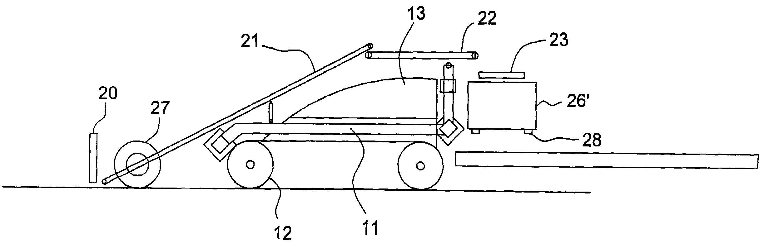
[0021]The machine of this invention comprises a main frame 11, which can be equipped with tracks 12, as shown in the drawings, or with wheels, and is powered by a power unit assembled on the frame and represented generically in 13.

[0022]The gauge between the tracks 12, or the wheels, of the machine is equal to the distance between the lanes 15 which divide the cultivated beds 16 in the greenhouse (FIGS. 7 and 8).

[0023]The main frame 11 comprises at least a horizontal beam 17 facing crossways to the forward and work direction of the machine, and on the beam 17 a secondary frame 18 is mounted which moves in the direction crossways to the forward direction of the machine.

[0024]In the example given, the secondary frame 18 has at least one transverse arm 18 configured to connect to and slide on at least one transverse beam 17 of the main frame 11 and holds, from the front towards the rear of the machine, a cutting bar 20, a first moving belt 21, a second mobile belt 22 and at least one r...


PUM

PropertyMeasurementUnit
distanceaaaaaaaaaa
heightaaaaaaaaaa
time to timeaaaaaaaaaa

Abstract

A machine for harvesting and boxing leaf vegetables cultivated in greenhouses, comprises a main frame (11) holding a front cutting bar, first and second moving belts (21, 22) for transferring the product longitudinally from the cutting bar towards the rear, and a platform supporting workers and a number of pallets of boxes. At least one transporter (23) is provided at the rear of the machine and positioned transversally to the forward direction of the machine, and designed to receive the product from the second moving belt and to deposit the product in the boxes. An operating group (30) comprising the front cutting bar (20), the first and second moving belts (21, 22) and the at least one transporter (23) can be moved with a secondary frame between a central position and a protruding lateral position from at least one side relative to the main frame.

Description

CROSS REFERENCE TO RELATED APPLICATIONS[0001]This application claims the benefit of priority under 35 U.S.C. § 119 of Italian Patent Application No. BS 2006 A 000183 filed Oct. 6, 2006, the entire contents of which are incorporated herein by reference.FIELD OF THE INVENTION[0002]The present invention concerns a machine for mechanized harvesting of leaf vegetables, such as lettuce, spinach and the like, in particular in greenhouse cultivations.BACKGROUND OF THE INVENTION[0003]A type of self-propelled machine for harvesting and boxing leaf vegetables that principally comprises a supporting frame with wheels or tracks and, on the frame, a front cutting bar associated with means for transferring the harvested product longitudinally towards boxes placed on a flat area at the rear of the machine is already known. The cutting bar can use a belt or alternating blades, but in either case it is arranged in the same way as the transferring devices, on the frame axis, in line with the forward d...

Claims


Application Information

Patent Timeline
Patent Type & Authority Patents(United States)
IPC IPC(8): B65B5/06
CPCA01D45/26
Inventor MOLA, ENRICO
Owner MOLA ENRICO
Why Eureka
Try Eureka