Automatic transmission control system
a transmission control and automatic technology, applied in the direction of gearing control, gearing element, belt/chain/gearing, etc., can solve the problem of determining the failure of the inhibitor switch, the error signal is output, and the gear shift lever may be determined in error
- Summary
- Abstract
- Description
- Claims
- Application Information
AI Technical Summary
Benefits of technology
Problems solved by technology
Method used
Image
Examples
second embodiment
[0145]FIG. 8 shows an automatic transmission control system according to the invention.
[0146]The automatic transmission 110, as referred to this embodiment, is of a four-speed type which includes, as clearly shown in FIG. 9, a torque converter 120 and a hydraulic transmission gearbox 150. The torque converter 120 has an input shaft 130 joined to an output shaft of an automotive engine (not shown) and an output shaft 140 jointed to the hydraulic transmission gearbox 150. The torque converter 12 has installed therein a pump impeller 31 (i.e., a fluid coupling), turbine runner 32, and a stator 33 disposed between the pump impeller 31 and the turbine runner 32. The pump impeller 31 faces the turbine runner 32 and connects with the input shaft 130 of the torque converter 120. The turbine runner 32 connects with the output shaft 140 of the torque converter 120. The stator 33 works to rectify the torque converter oil.
[0147]The torque converter 120 also includes a lock-up clutch 160 which w...
first embodiment
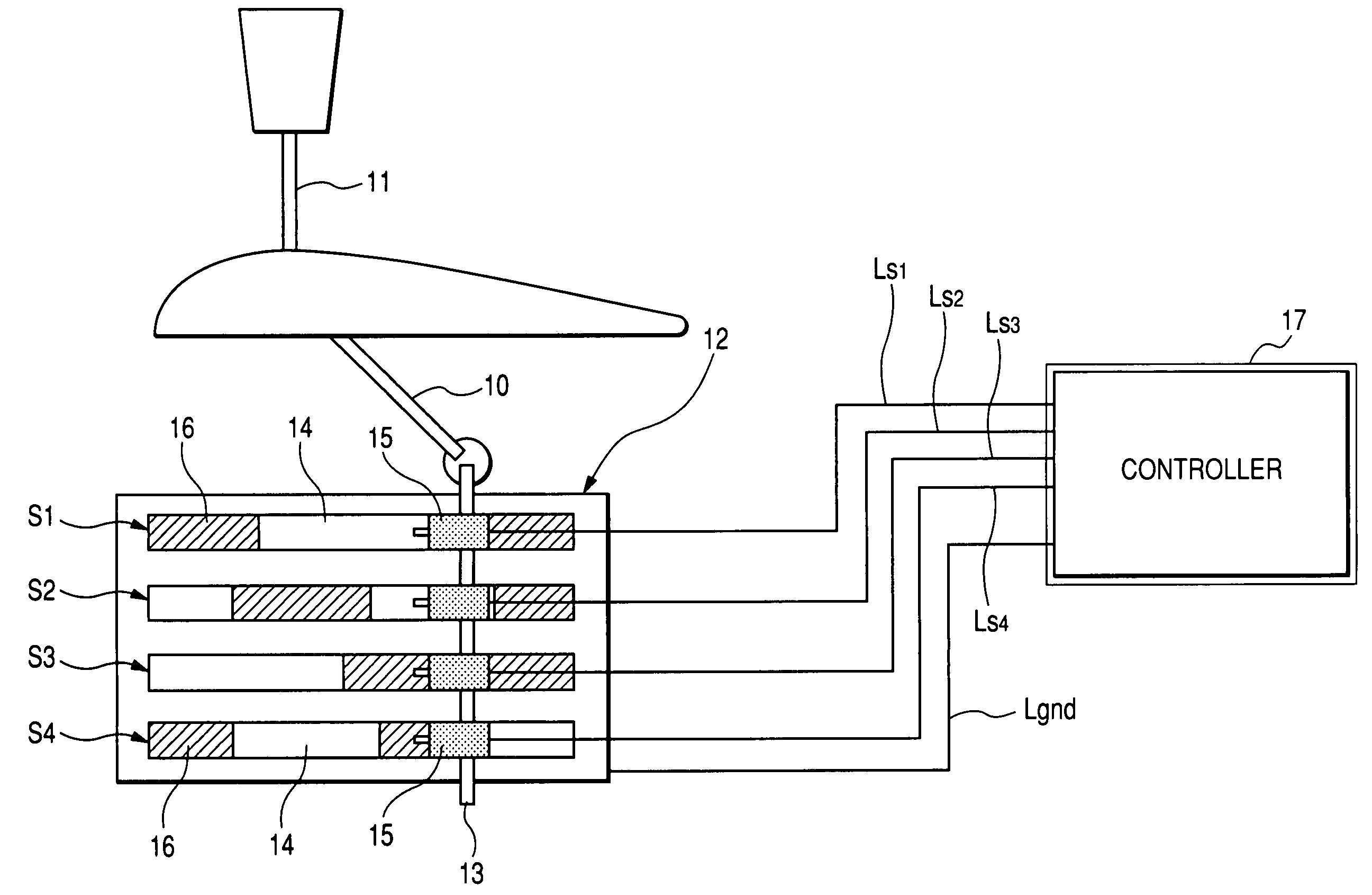
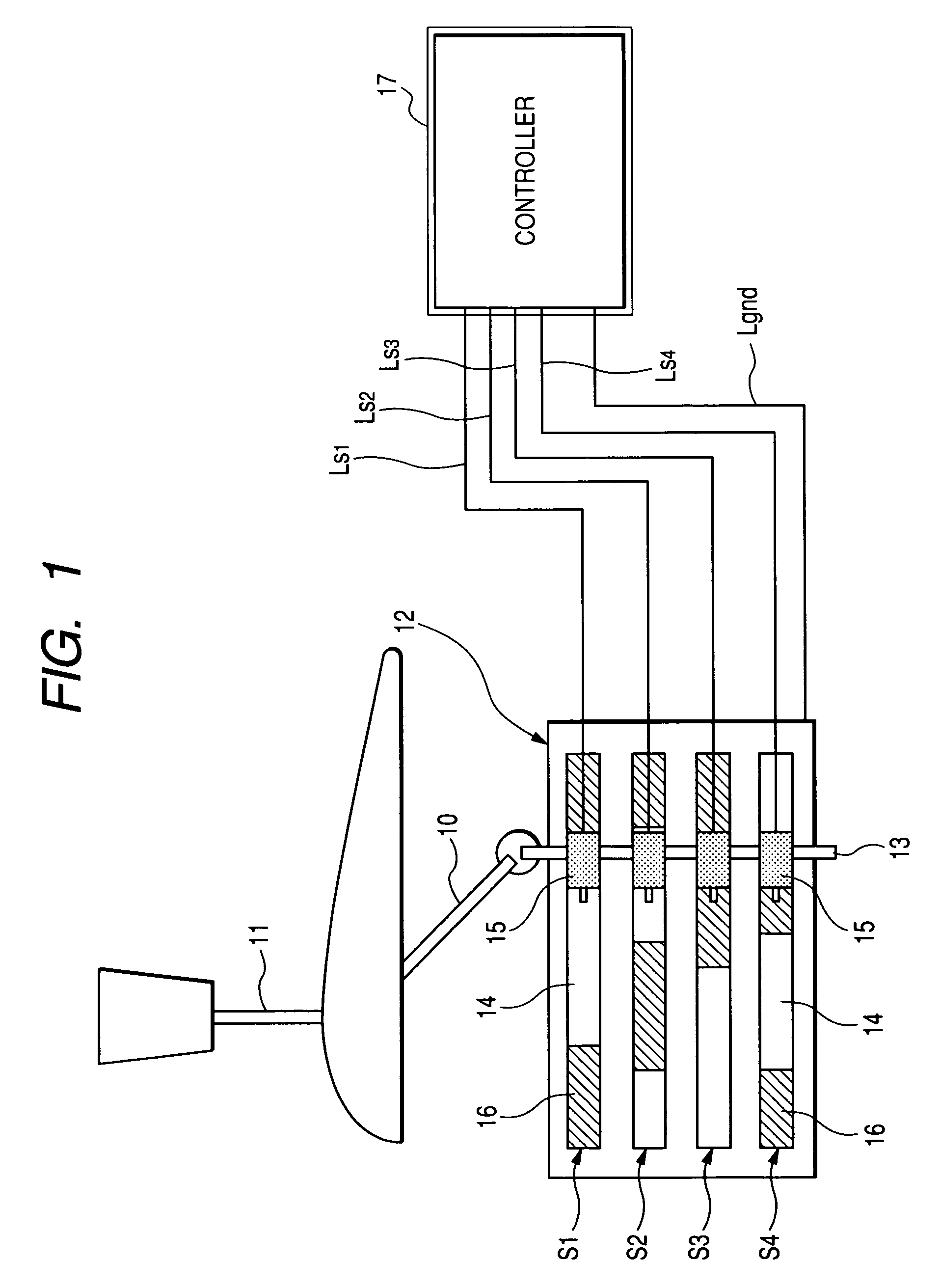
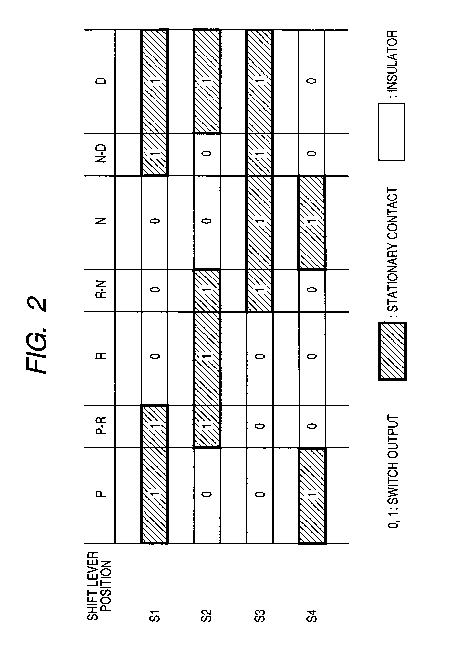
[0156]The automatic transmission 110 is designed to change the gear ranges in a shift pattern of P-R-N-D. The shift lever position sensor 12, like that in the first embodiment, is designed to monitor a total of seven shift lever positions: the P position, the R position, the N position, the D position, the P-R position, the R-N position, and the N-D position.
[0157]The seven shift lever positions, as described above, are each expressed by a three-bit code.
[0158]Generally, it is possible for the three-bit code to represent 23=eight (8) binary patterns. The number of positions of the gear shift lever 11 to be monitored by the shift lever position sensor 12 is, as described above, seven (7). The AT control system of this embodiment does not use one of the eight bit patterns in determining the position of the gear shift lever 11. Specifically, the AT control system is designed to use seven of the eight bit patterns for representing the positions of the gear shift lever 11 except one, as ...
third embodiment
[0228]the invention will be described below.
[0229]FIGS. 22 and 23 show modifications of the gear change initiation decision and the gear change completion / gear holding decision, as made in the programs of FIGS. 19 and 20.
[0230]While the AT-ECU 30 of the second embodiment works to observe a gear change action (i.e., initiation of a gear change or holding of a selected gear) of the automatic transmission 110 when the deemed D-position hydraulic transmission control is performed by monitoring a change in the input shaft speed Nt, the AT-ECU 30 of this embodiment is designed to achieve such an observation using a change in gear ratio GR of the automatic transmission 110. The gear ratio GR is mathematically determined in the AT-ECU 30 by a ratio of the input shaft speed Nt, as measured by the input shaft speed sensor 28, to the output shaft speed No, as measured by the output shaft speed sensor 29 (i.e., GR=Nt / No).
[0231]The AT-ECU 30 performs the programs illustrated in FIGS. 22 and 23 i...
PUM
 Abstract
Description
Claims
Application Information
 - R&D
- Intellectual Property
- Life Sciences
- Materials
- Tech Scout
- Unparalleled Data Quality
- Higher Quality Content
- 60% Fewer Hallucinations
Browse by: Latest US Patents, China's latest patents, Technical Efficacy Thesaurus, Application Domain, Technology Topic, Popular Technical Reports.
© 2025 PatSnap. All rights reserved.Legal|Privacy policy|Modern Slavery Act Transparency Statement|Sitemap|About US| Contact US: help@patsnap.com


