Upper rotor control system for a counter-rotating rotor system

Inactive Publication Date: 2009-09-08
SIKORSKY AIRCRAFT CORP
View PDF5 Cites 34 Cited by
  • Summary
  • Abstract
  • Description
  • Claims
  • Application Information

AI Technical Summary

Benefits of technology

[0012]The present invention therefore provides a compact, light-weight upper rotor control system for a counter-rotating rotor system.

Problems solved by technology

Buckling stability of the long rods requires a relatively heavy, large diameter solution which may be difficult to package within the rotor shaft.

Method used


Image

  • Upper rotor control system for a counter-rotating rotor system
  • Upper rotor control system for a counter-rotating rotor system
  • Upper rotor control system for a counter-rotating rotor system

Examples


Embodiment Construction

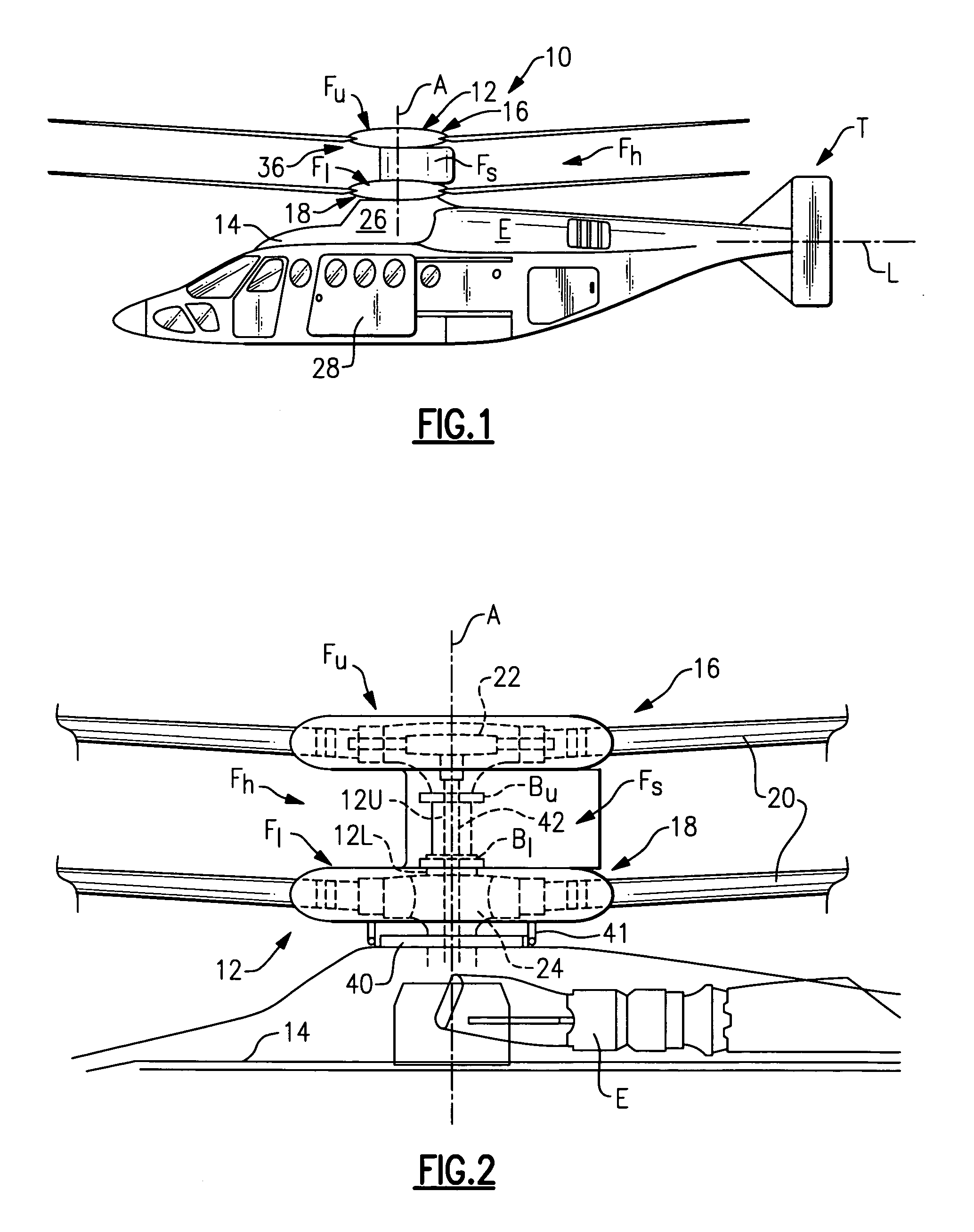
[0025]FIG. 1 illustrates an exemplary vertical takeoff and landing (VTOL) rotary-wing aircraft 10 having a dual, counter-rotating, coaxial rotor system 12 which rotates about an axis of rotation A. The aircraft 10 includes an airframe 14 which supports the dual, counter rotating, coaxial rotor system 12 as well as an optional translational thrust system T which provides translational thrust generally parallel to an aircraft longitudinal axis L. Although a particular aircraft configuration is illustrated in the disclosed embodiment, other counter-rotating, coaxial rotor systems will also benefit from the present invention.

[0026]A main gearbox 26 which may be located above the aircraft cabin drives the rotor system 12. The translational thrust system T may be driven by the same main gearbox 26 which drives the rotor system 12. The main gearbox 26 is driven by one or more engines (illustrated schematically at E). As shown, the main gearbox 26 may be interposed between the gas turbine e...


PUM


Abstract

An upper rotor control system is contained within an upper rotor shaft and upper hub assembly of a contra-rotating rigid rotor system. A collective servo assembly includes a hydraulic actuator that provides collective pitch to all blades through axial extension / retraction of the control rod relative the upper rotor shaft for collective pitch control of the rotor blades. The collective servo assembly includes a spherical bearing for attachment of the control rod to aircraft structure. An X-Y positioner assembly includes a bearing arrangement which allows the shaft to rotate, while the X-Y positioner assembly remains non-rotational therein. The X-Y positioner assembly includes a multitude of hydraulic actuators, orthogonally positioned, to tilt the control rod about the spherical bearing off the axis of rotation of the upper rotor shaft for cyclic pitch control of the rotor blades.

Description

BACKGROUND OF THE INVENTION[0001]The present invention relates to a rotor control system for a rotary-wing aircraft, and more particularly to an upper rotor control system for a counter-rotating rotor system.[0002]Control of a rotary-wing aircraft is affected by varying the pitch of the rotor blades individually as the rotor rotates and by varying the pitch of all of the blades together. These are known respectively as cyclic and collective pitch control. Blade pitch control of a rotary wing aircraft main rotor is typically achieved through a swashplate assembly which transfers the motion of non-rotating control members to the rotating members.[0003]The swash plate assembly is typically concentrically mounted about a rotor shaft. The swash plate assembly generally includes two rings connected by a series of bearings with one ring connected to the airframe (stationary), and the other ring connected to the rotor hub (rotating). The rotating ring is connected to the rotor hub through a...

Claims


Application Information

Patent Timeline
Patent Type & Authority Patents(United States)
IPC IPC(8): B64C27/80
CPCB64C27/10B64C27/32B64C27/48B64C27/605B64C2027/8236
Inventor SCHMALING, DAVID N.CABRERA, PEDRO L.
Owner SIKORSKY AIRCRAFT CORP
Why Eureka
Try Eureka