Method for producing an adhesive closure element

a technology of closure element and adhesive, which is applied in the field of method of producing an adhesive closure element, can solve the problems of multiple use, and achieve the effect of reducing production costs, improving production efficiency, and reducing production costs

Inactive Publication Date: 2009-09-08
APLIX MICROSYST
View PDF23 Cites 4 Cited by
  • Summary
  • Abstract
  • Description
  • Claims
  • Application Information

AI Technical Summary

Benefits of technology

[0008]The invention, therefore, provides a technically efficient and also cost-effective production method, in which the method set-up necessary for this purpose can be produced at a low outlay and, ultimately, for an at least equivalent final product, production can be carried out more simply and more inexpensively than in the methods known hitherto. The goals of the invention is achieved by a method for producing an adhesive closure element from thermoplastic in the form of an extruded pin strip, on which a multiplicity of hooking measures in the form of pins with pin heads thickened at the end are disposed and which is fed from a sheet die to the nip between a thermally controlled forming roller and a likewise thermally controlled pressure and smoothing roller. A forming roller with a metallic basic body is equipped on its surface with a rubber layer that, on its circumference, has pin holes, introduced by laser treatment, as blind holes, into which a film strip is pressed by the pressure of the thermally controlled pressure and smoothing roller. As a result, pins are produced, and the pin strip is drawn off by a likewise thermally controlled draw-off roller, and, in the case of low strip running speeds of the pin strip, the heads of the pins are formed by temperature and pressure by a heated and Teflon-coated pressure roller. But, in the case of high strip running speeds of the pin strip, the pin heads are produced, without contact, by a plasma device and its plasma arc.

Problems solved by technology

There is, furthermore, the possibility of the multiple use even of a laser-treated rubber layer, in that the latter is overturned and laser-treated again.

Method used


Image

  • Method for producing an adhesive closure element
  • Method for producing an adhesive closure element
  • Method for producing an adhesive closure element

Examples


Embodiment Construction

:

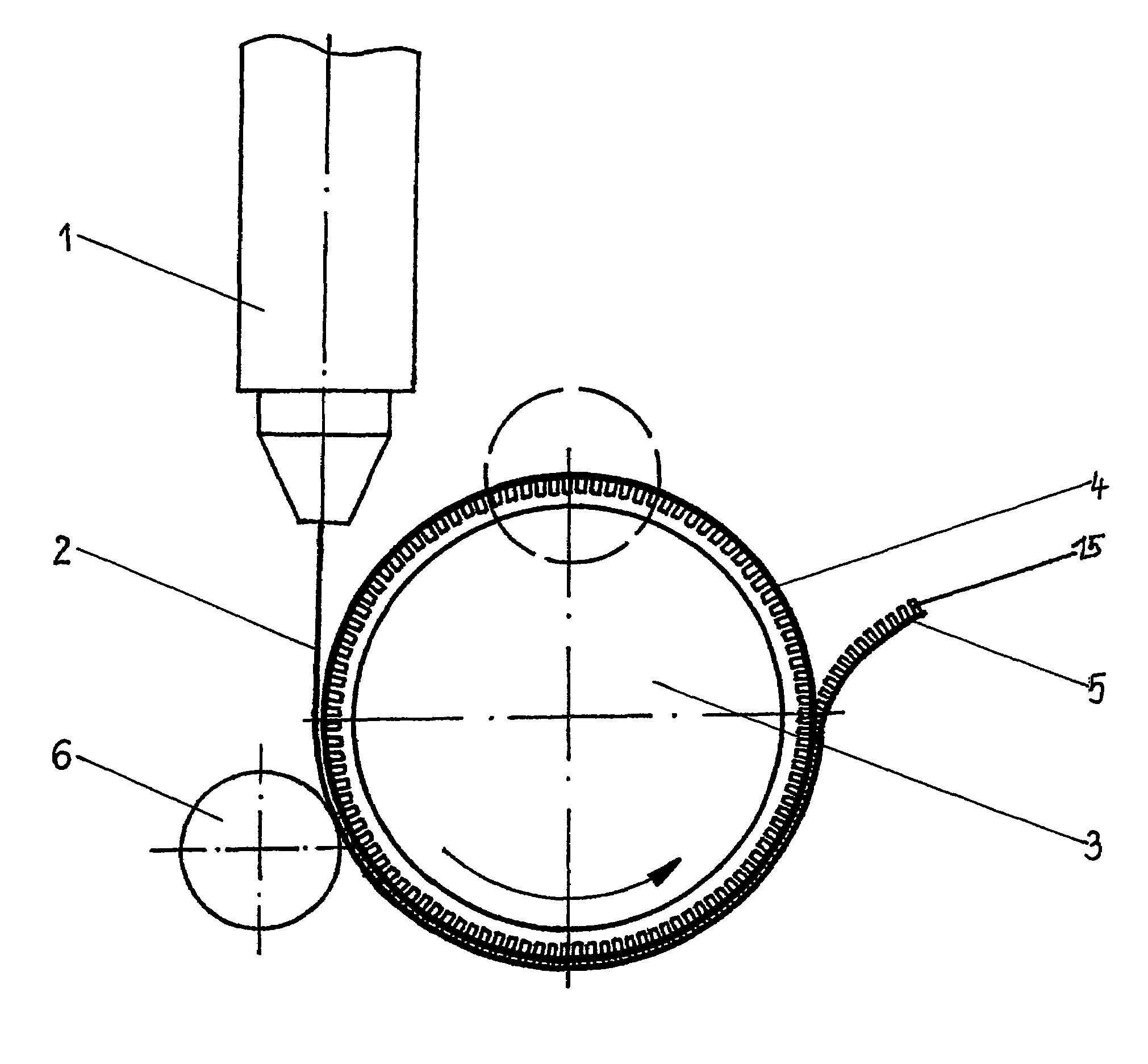
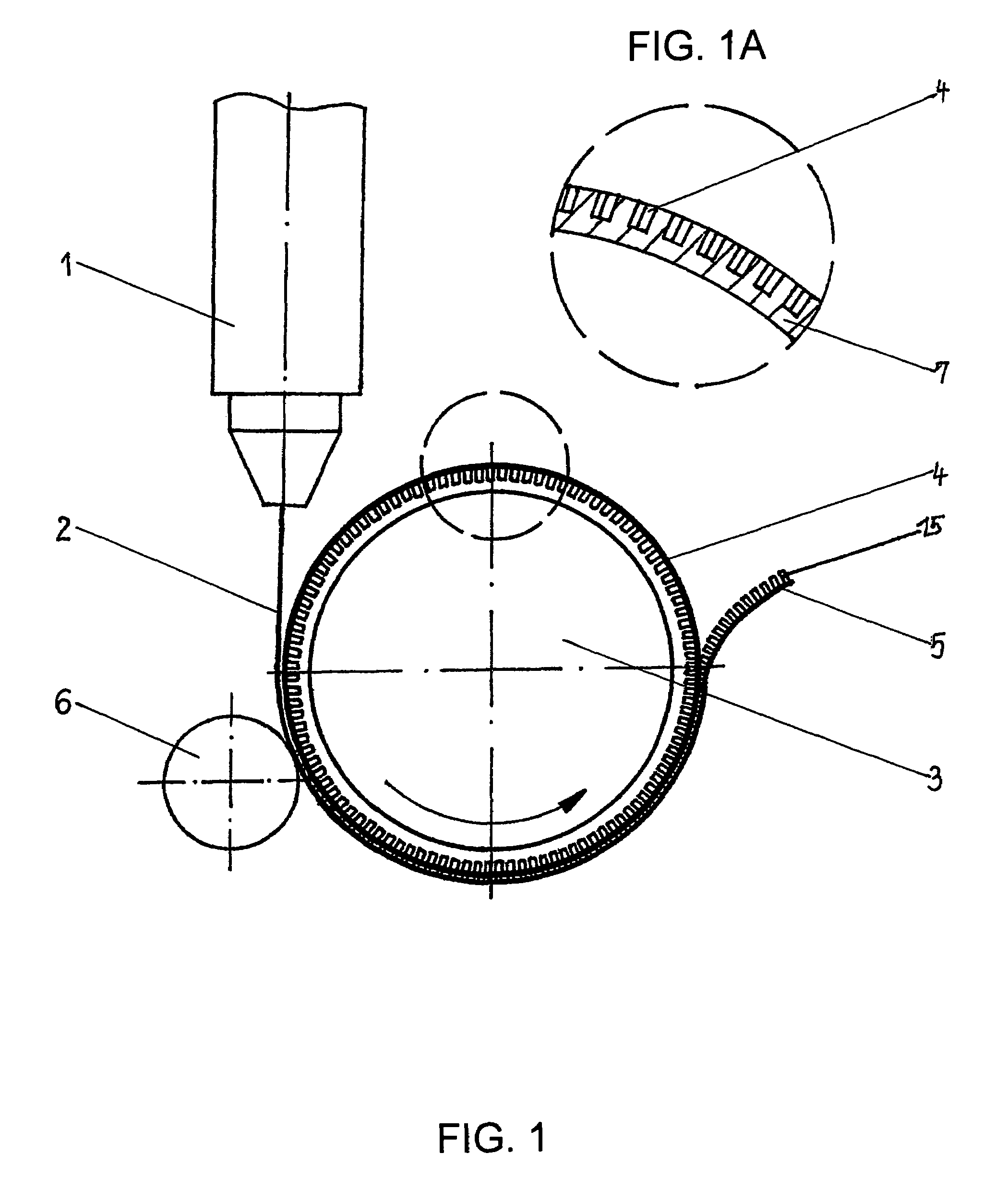
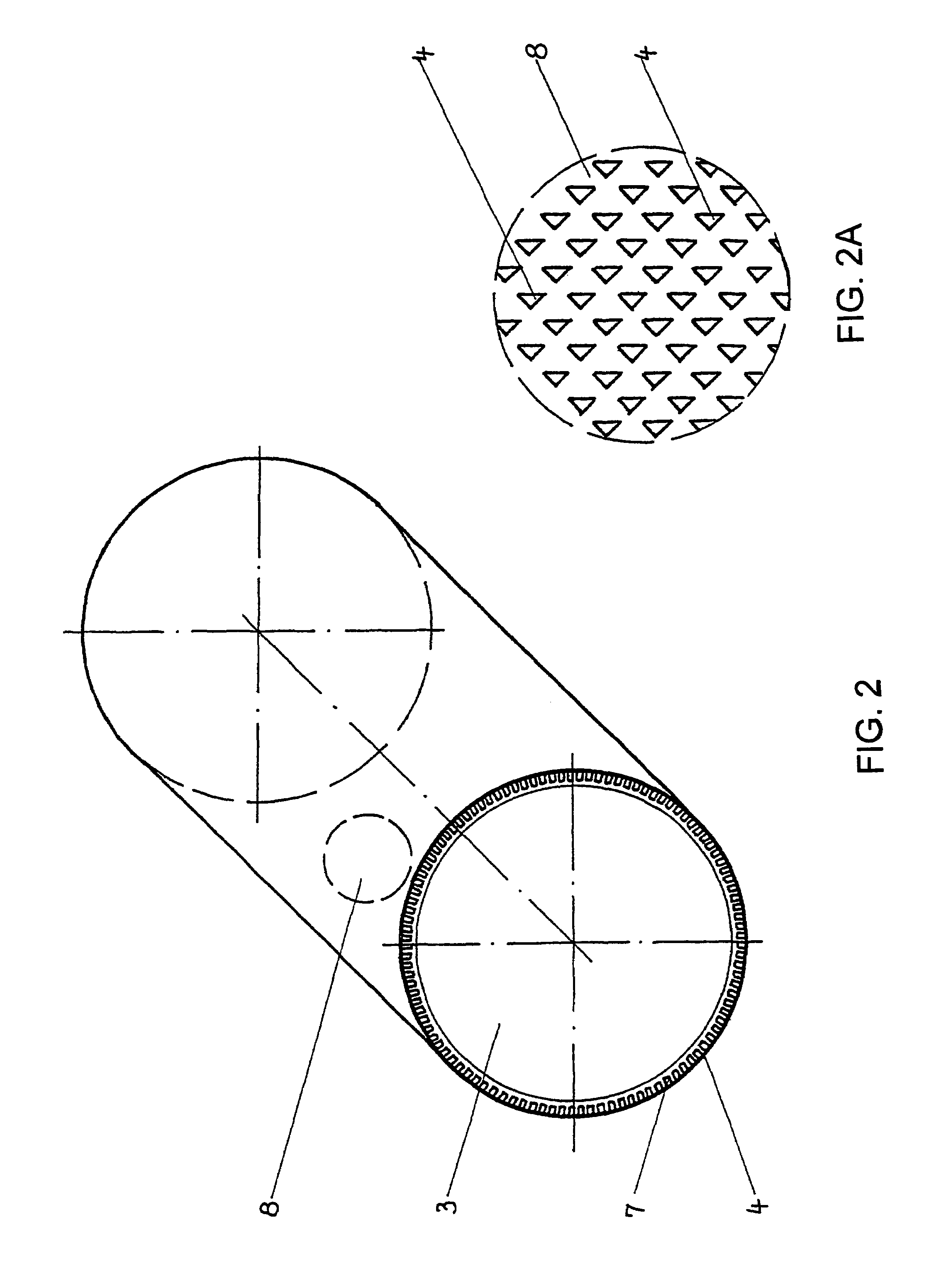
[0023]Plastic granulate is fused in an extruder in the conventional way and is fed as a film strip 2 to a thermally controlled forming roller 3 via a sheet die 1. This thermally controlled forming roller 3 is equipped on its outer circumference in a form-fitting manner with a rubber layer 7. For this purpose, the thermally controlled forming roller 3 is expediently roughened for the secure reception of the rubber layer 7. The rubber layer 7, as a sheet-like strip, is provided with pin holes 4, especially evident from the detail 8 of the surface of the forming roller 3, which, however, are designed as a blind hole and therefore do not pierce through the rubber layer 7. The rubber layer 7 possesses, distributed on its circumference, laser-treated orifices as the pin holes 4, which run slightly conically downward, that is to say toward the bottom. According to FIG. 5, multiconfigured end faces of the pin holes 4 are shown by way of example, which are thus put into practice by virtue o...


PUM

PropertyMeasurementUnit
thicknessaaaaaaaaaa
speedsaaaaaaaaaa
speedsaaaaaaaaaa

Abstract

The invention relates to a method for producing an adhesive closure element made of a thermoplastic synthetic material, by means of an extruder, which is produced without the need for screens, using a tempered forming cylinder (3) coated in rubber and a pressure cylinder in the form of a tempered pressure and smoothing cylinder. According to the invention, the synthetic material of a strip of film (2) is compressed by a wide split nozzle (1) of the extruder into pin holes (4) embodied as pocket holes in a rubber layer (7) which is arranged on the tempered forming cylinder (3), said layer of rubber (7) and the pin holes being provided with a teflon covering. The pin strip (5) is guided by means of a tempered withdrawal cylinder (10) between a gap with a gap with a pression cylinder (9) heated to a temperature greater than 230° C. and covered with PTFE at a low speed of between approximately 1 m/min. and 20 m/min. Alternatively, the pin heads (11) are formed by a plasma device (13) or by a plasma are (14) produced therefrom and the strip is displaced at a speed of between 12 m/min. and 200 m/min.

Description

BACKGROUND OF THE INVENTIONField of the Invention[0001]The invention relates to a method for producing an adhesive closure element, said method, without the use of screens, but employing a rubber-coated roller, being capable of producing a multiplicity of hooking means in the form of pins formed on a forming roller, a thermoplastic being fed by an extruder, via a sheet die, to the pin roller equipped with special features, and subsequently, depending on the magnitude of the production speed, either undergoing a head-forming of the pins by pressure by means of a thermally controlled pressure roller, which is already conventionally known in the production of broad films, in conjunction with a deflecting roller or, alternatively, running, free of contact, through a plasma field in which the head formation of the pins takes place. The method according to the invention is applied in the production of adhesive closure elements which are in multifarious use, preferably as fastening means w...

Claims


Application Information

Patent Timeline
Patent Type & Authority Patents(United States)
IPC IPC(8): B29C43/46A44B18/00B29C33/58B29C43/22B29C48/07B29C48/305B29C48/35B29C59/02B29C59/04B29K101/12B29L7/00
CPCA44B18/0049B29C33/58B29C43/222B29C47/0021B29C59/022B29C59/04B29C43/46B29C2043/461B29L2031/729B29C47/32B29C48/08B29C48/35B29C48/07
Inventor JAHN, WERNERSEIFERT, GUNTMAR
Owner APLIX MICROSYST
Why Eureka
Try Eureka