Optical system for endoscopes

an endoscope and optical system technology, applied in the field of optical systems for endoscopes, can solve the problems of reducing the diameter of the endoscope, not being realistic, and increasing the total length of the illumination optical system b>6/b>

Active Publication Date: 2009-09-08
OLYMPUS CORP
View PDF13 Cites 69 Cited by
  • Summary
  • Abstract
  • Description
  • Claims
  • Application Information

AI Technical Summary

Problems solved by technology

Therefore, the increasing of the curvature of the concave surface of the negative lens 2 goes against a demand for the reduction of the diameter of the endoscope, and is not realistic.
However, when the single fiber rod 5 is lengthened, the total length of the illumination optical system 6 increases, and this cannot satisfy a demand for the reduction of the total length of the optical system in the endoscope.
The above-described illumination optical system is usually used in combination with an observation optical system having a field angle of 120° to 140°, but when the illumination optical system is used in combination with the observation optical system having a field angle of 150° or more, there occurs a disadvantage in that the visual field periphery (vicinity of an inner edge of an observable area (visual field)) of the observation optical system darkens, and cannot practically be observed.
However, it can be confirmed through experiments that one feels that the illumination optical system is unsuitably dark for the system which illuminates the visual field of the observation optical system whose angle of field exceeds 100°.
However, when the angle of emission exceeds 55°, the illuminance rapidly drops, and darkness becomes conspicuous.
Therefore, although the illumination system has a high absolute illuminance, it is unsuitable in a system for illuminating the visual field of an observation optical system having a field angle of 150° or more, since the change of the illuminance is large, thereby giving an impression that the visual field periphery is dark.
However, when the system has the above-described light distribution characteristics, even a non-observed area outside the visual field area is illuminated, and this is not desirable with regard to illumination efficiency.
To realize a wide-angle illumination system, the change of the illuminance is comparatively moderate, and the absolute illuminance needs to have a value which is not less than a certain value in the visual field periphery, but the above-described illumination optical system does not satisfy this requirement.
However, it is difficult to improve the balance of the light distribution at the time when the distal end surface of the endoscope comes close to the object up to a sufficiently satisfactory level of wide-angle illumination only by the positional relation between the observation optical system and the illumination optical system and the quantity of emitted light.

Method used


Image

  • Optical system for endoscopes
  • Optical system for endoscopes
  • Optical system for endoscopes

Examples


embodiment 2

[0126]The basic arrangement of the endoscope optical system of Embodiment 2 is substantially the same as that of Embodiment 1, and is different from that of Embodiment 1 in that the convex surface of the illumination optical system 10b is finished as a polished surface. The illumination optical system 10b has light distribution characteristics f(θ) shown in FIG. 14. Differential values df(θ) / dθ of the light distribution characteristics f(θ) are shown in FIG. 15. As shown in FIG. 15, the differential value df(θ) / dθ of the light distribution characteristics f(θ) retains a value of 0.02 or less at an angle θ of emission in the range of 5° to 85°, and further retains a value of 0.015 or less at the angle θ of emission in the range of 65° to 80°. Therefore it is possible to give the impression that no change of brightness is felt from the visual field center to the periphery. Furthermore, the illuminance ratio f(θ) at an emission angle θ of 80° is 0.11, and the system also has a superior...

embodiment 3

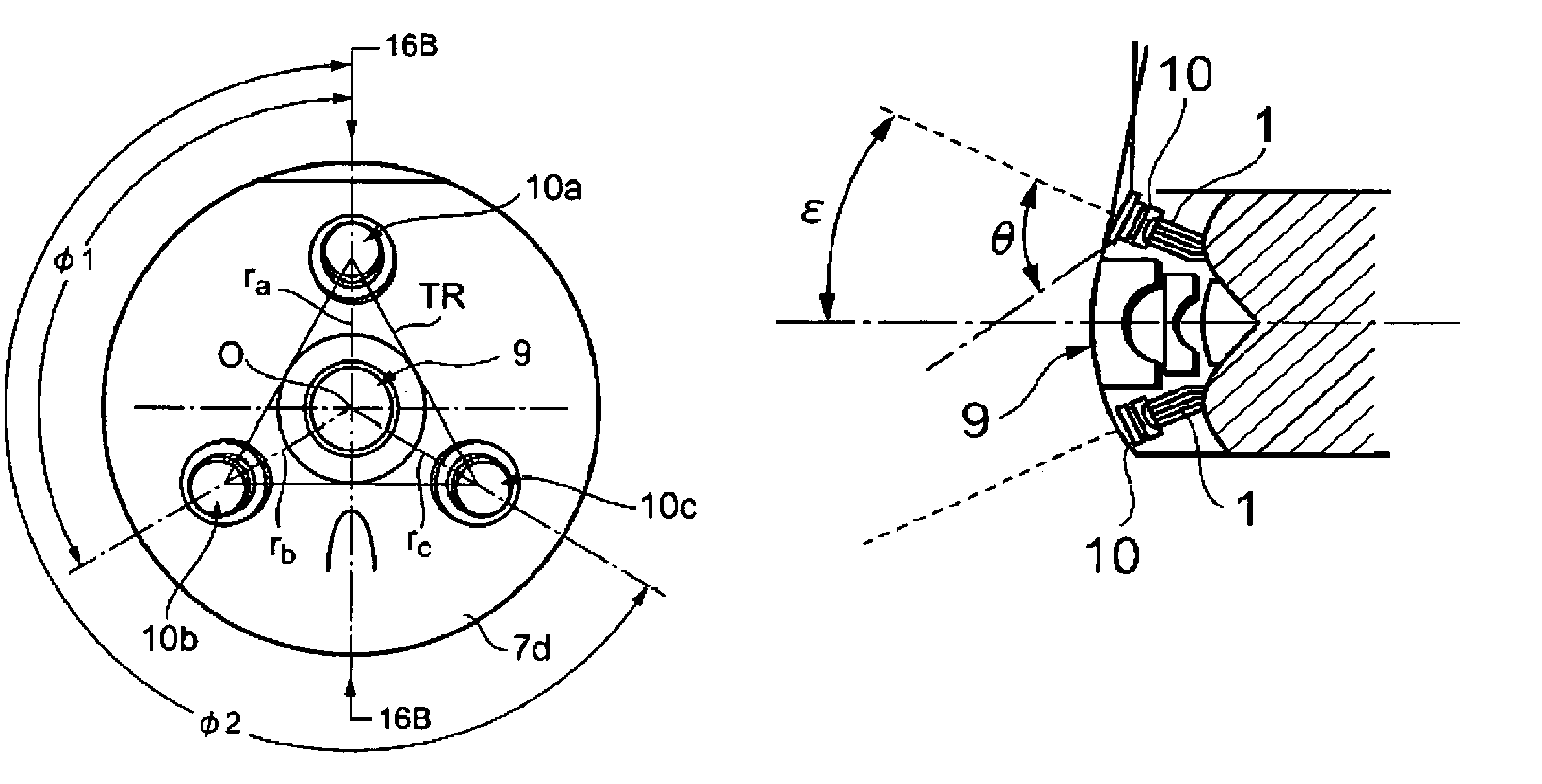
[0129]FIGS. 16A and 16B are diagrams showing Embodiment 3 of the present invention, FIG. 16A is a diagram of a layout of an endoscope optical system as viewed from the object side, and FIG. 16B is a diagram showing a part of a section along line 16B-16B of FIG. 16A.

[0130]The endoscope optical system of Embodiment 3 is provided with an observation optical system 9 having a field angle of 170°, and three illumination optical systems 10a, 10b and 10c. The distal end surface 7d of the endoscope is formed into a bullet shape in which the observation optical system is at the vertex. As viewed from the front (object side), the three illumination optical systems 10a, 10b and 10c are arranged in such a manner as to surround the observation optical system 9. The three illumination optical systems 10a, 10b and 10c are oblique in such a manner as to direct emission surfaces thereof outwardly with respect to the optical axis of the observation optical system in accordance with the bullet shape o...

embodiment 4

[0140]FIG. 21 is an explanatory view showing the layout of an endoscope optical system as viewed from the object side according to Embodiment 4 of the present invention.

[0141]The endoscope optical system of Embodiment 4 is provided with an observation optical system 9 having a field angle of 160°, and three illumination optical systems 10a, 10b, and 10c. The distal end surface 7d of the endoscope is formed into a substantially flat surface. As viewed from the front (object side), the three illumination optical systems 10a, 10b and 10c are arranged in such a manner as to surround the observation optical system 9. Each of the three illumination optical systems 10a, 10b and 10c comprise one positive lens as shown in FIG. 7. The systems satisfy the conditions (1) and (2), and are appropriate as those for combined use with an observation optical system having a large angle of field.

[0142]Moreover, as shown in FIG. 21, the three illumination optical systems 10a, 10b and 10c are arranged i...


PUM


Abstract

An optical system for an endoscope can be used by being disposed in the distal end portion of the endoscope, the optical system having a plurality of illumination optical systems, which allow light emitted from a light source to diverge, and an observation optical system, in which at least one of the plurality of illumination optical systems satisfies the following formula (1):0≦−df(θ) / dθ≦0.025, 10°≦θ≦85°  (1),wherein θ denotes an angle of emission from a center of the illumination optical system, and f(θ) denotes a value obtained by standardizing, at an illuminance at a time when the angle θ of emission is 0°, an illuminance distribution (spherical light distribution characteristics) at a time when a spherical object is illuminated by the illumination optical system.

Description

CROSS-REFERENCE TO RELATED APPLICATIONS[0001]This application claims benefit under 35 U.S.C. §119 of Japanese Patent Application No. 2004-256,904, filed in Japan on Sep. 3, 2004, the contents of which are hereby incorporated by reference.BACKGROUND OF THE INVENTION[0002]1. Field of the Invention[0003]This invention relates to an optical system for an endoscope, particularly to an optical system for use in the distal end of the endoscope.[0004]2. Description of the Related Art[0005]Since the inside of a body cavity when it is the observation object of a medical endoscope is dark, the inside needs to be illuminated, when it is observed. To perform the illumination using an endoscope, light exiting from a light source is generally guided to a distal end portion of the endoscope by a light guide fiber bundle disposed in the endoscope, and an observation object in the body cavity is illuminated via an illumination optical system disposed in the distal end portion to illuminate a visual f...

Claims


Application Information

Patent Timeline
Patent Type & Authority Patents(United States)
IPC IPC(8): A61B1/06
CPCA61B1/07A61B1/00096
Inventor HOMMA, HIROYUKI
Owner OLYMPUS CORP
Why Eureka
Try Eureka