Digital phase detector and a method for the generation of a digital phase detection signal

a digital phase detection and detector technology, applied in the direction of measurement devices, instruments, and angle demodulation by phase difference detection, can solve the problems of severely limited phase resolution thus achievable, and the speed of electronic components is limited in practice, so as to achieve high phase resolution

Active Publication Date: 2009-09-08
NAT SEMICON GERMANY
View PDF3 Cites 8 Cited by
  • Summary
  • Abstract
  • Description
  • Claims
  • Application Information

AI Technical Summary

Benefits of technology

[0007]It is an object of the present invention to provide a phase detection by means of which the phasing of an input clock signal can be detected with reference to a sampling clock signal with high phase resolution.
[0020]A preferred use of the phase detector and / or the phase detection method ensues with the implementation of the phase detector in a PLL. In this application the increased phase resolution of the phase detector can advantageously be used to improve the performance characteristics of the PLL concerned.

Problems solved by technology

The phase resolution thus achievable is however severely limited by the linearity of the analog phase detector and also the resolution of the analog-digital converter.
The phase resolution is then definitively determined by the sampling rate (frequency of the sampling clock signal), wherein, however, the maximum sampling frequency is limited in practice by the speed of the electronic components used in the sampling circuit.

Method used


Image

  • Digital phase detector and a method for the generation of a digital phase detection signal
  • Digital phase detector and a method for the generation of a digital phase detection signal
  • Digital phase detector and a method for the generation of a digital phase detection signal

Examples


Embodiment Construction

)

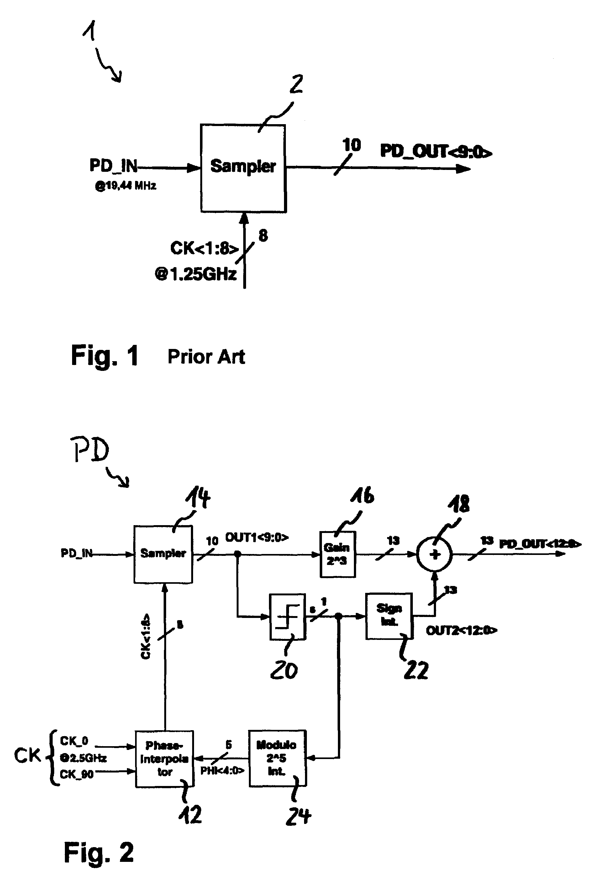
[0039]FIG. 1 demonstrates the function of a conventional digital phase detector 1 generating a digital phase detection signal PD_OUT, which specifies the phasing of an input clock signal PD_IN supplied to the phase detector 1 with reference to a higher frequency sampling clock signal CK supplied to the phase detector 1. The anticipated, or average, frequencies of the signals PD_IN and CK are specified in FIG. 1 in an exemplary manner, and in this example differ from each other by a factor of approximately 64. The phase detector 1 consists of a sampling device 2, which generates the phase detection signal PD_OUT in a binary representation. If a single phase sampling signal CK were to be used one here, then, in accordance with the selected “oversampling”, a signal PD_OUT with a resolution of 6 bits could be provided (26=64). In the example represented the sampling clock signal CK is however inputted with eight phases arranged equidistant to one another, which in FIG. 1 is symbolised ...


PUM


Abstract

The present invention concerns a digital phase detector (PD) and also a method for digital phase detection, as can in particular be used e.g. in a so-called phase locked loop (PLL). According to the invention a digital phase detection signal (PD_OUT) is obtained, which specifies the phasing of an input clock signal (PD_IN) with reference to a higher frequency sampling clock signal (CK). In order hereby to overcome the limitation of the phase resolution as a result of a limited performance capability, in particular limited speed of the electronic components of a sampling device (14), a new kind of concept is used, in which the sampling clock signal (CK) is not immediately used for sampling (14), but is subjected beforehand to a digitally adjustable phase displacement (12). There originates an “auxiliary sampling clock signal” (CK<1:8>). The sampling (14) delivers a first, more significant digital component (OUT1<9:0>) of the phase detection signal (PD_OUT). Based on an evaluation of this first digital component (OUT1<9:0>) a phase displacement (12) is undertaken and a second digital component (OUT2<12:0>) of the phase detection signal (PD_OUT) is generated. The auxiliary sampling clock signal (CK<1:8>) is here adjustable in steps, which in each case are smaller than one period of the sampling clock signal (CK).

Description

BACKGROUND OF THE INVENTION[0001]1. Field of the Invention[0002]The present invention concerns a digital phase detector and also a method for digital phase detection, as can in particular be used e.g. in a so-called phase locked loop (PLL).[0003]In general terms a PLL serves the purpose of synchronising a controllable oscillator, which generates an output signal with an output frequency, with an input clock signal with an input frequency, by means of feedback. For this purpose the PLL comprises a phase detector or phase comparator, at whose input the input clock signal and the PLL output signal are present. A signal representing the respective phasing between these two signals is mainly used to control the oscillator via an active or passive, digital or analog filter (“loop filter”).[0004]2. Description of the Prior Art[0005]The areas of application for PLL circuits are many and varied. For example PLLs can be used for clock signal recovery from digital signal sequences, or for FM d...

Claims


Application Information

Patent Timeline
Patent Type & Authority Patents(United States)
IPC IPC(8): G01R25/00H03D13/00
CPCH03L7/093H03L7/091H03L7/087
Inventor WERKER, HEINZEBNER, CHRISTIAN
Owner NAT SEMICON GERMANY
Why Eureka
Try Eureka