Image interpolation device and a frame rate converter and image display apparatus using the same

a frame rate converter and interpolation device technology, applied in the direction of instruments, television systems, signal generators with optical-mechanical scanning, etc., can solve the problems of large quantities of arithmetic operations, inability to sharpen or clear images, and unnatural appearance of images in the motion of images, etc., to suppress erroneous detection, high interpolation accuracy, and simple circuit configuration

Active Publication Date: 2009-09-08
PANASONIC LIQUID CRYSTAL DISPLAY CO LTD +1
View PDF23 Cites 25 Cited by
  • Summary
  • Abstract
  • Description
  • Claims
  • Application Information

AI Technical Summary

Benefits of technology

[0027]According to the present invention, since pixel pairs closely correlated with one another with respect to an interpolation position within an interpolation frame, between an immediately previous frame of image signals and a current frame thereof, are detected and interpolation pixels of the interpolation frame are generated using the pixel pairs, motions of images between these frames can also be detected with a simple circuit configuration, and highly accurate interpolation frames responding to these motions can be generated.
[0028]Also, since a next interpolation frame can be generated considering edge information and motion information of the immediately previous interpolation frame, it is possible to generate a more accurate interpolation frame, to suppress erroneous detection, and thus to implement highly accurate frame rate conversion of image signals.

Problems solved by technology

Although applying hardware is the simplest way to implement the zeroth-order hold method, this method has the problem in that the occurrence of motion judder (clumsy motions) at the iterative sections of frames results in conspicuous unnaturalness appearing in the motions of images.
Also, the linear interpolation method has the problem in that since double after-image disturbance occurs at the edges of images, each entire image gives blurriness (lacks sharpness or clearness).
In addition, in the conventional interpolation method that uses motion compensation processing, pattern matching over the entire search area is required, which, in turn, requires great quantities of arithmetic operations.
For these reasons, the conventional interpolation method has the problem that since the arithmetic operations become very complex, a more complex and larger-scale configuration tends to be necessary.

Method used


Image

  • Image interpolation device and a frame rate converter and image display apparatus using the same
  • Image interpolation device and a frame rate converter and image display apparatus using the same
  • Image interpolation device and a frame rate converter and image display apparatus using the same

Examples


first embodiment

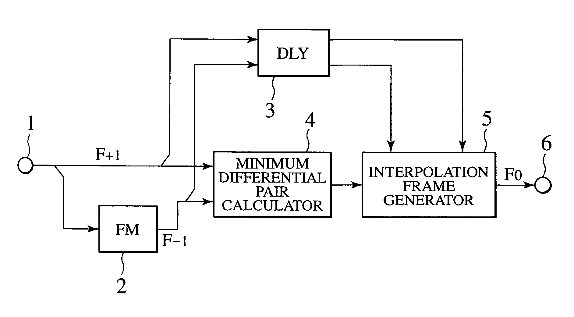
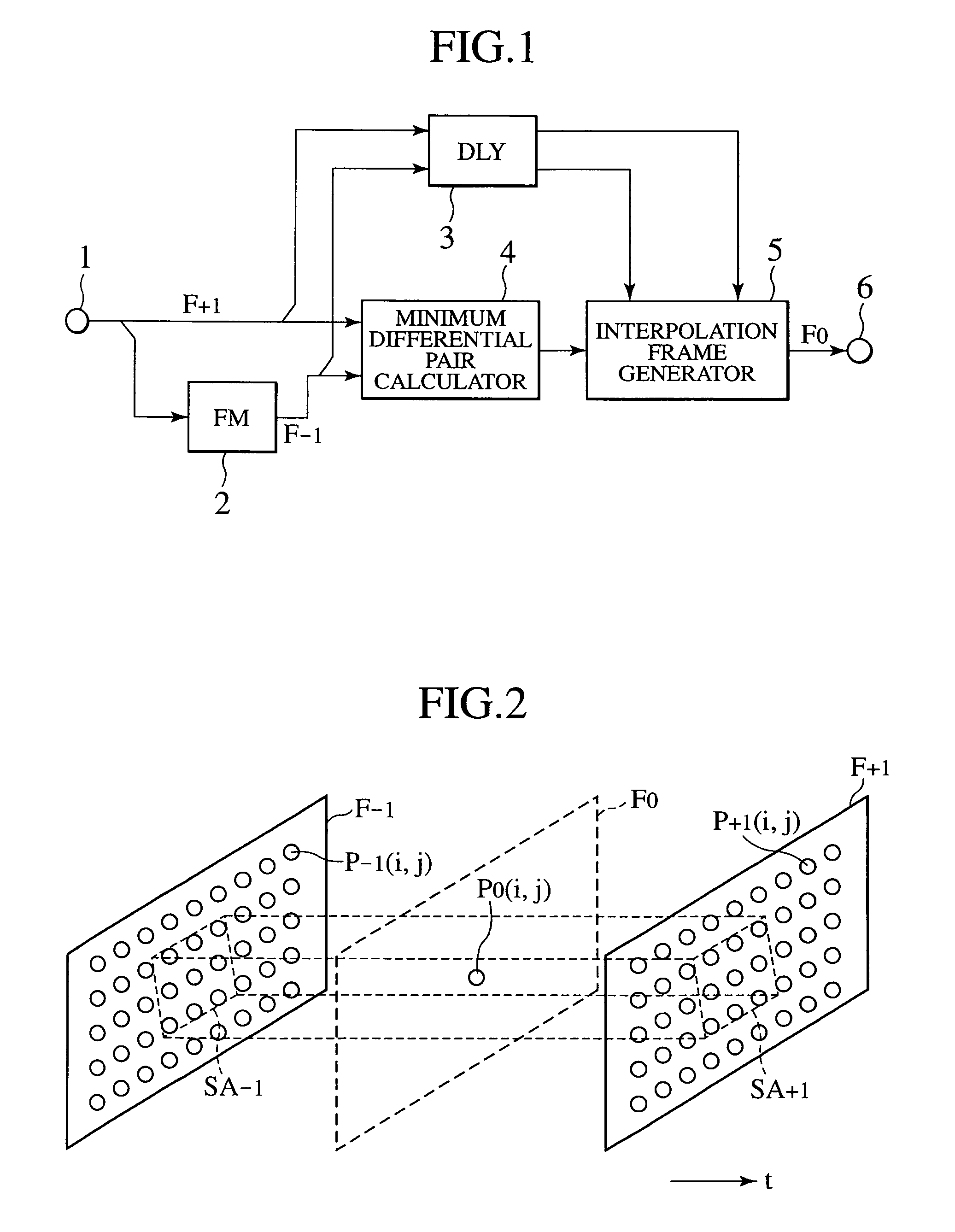
[0045]FIG. 1 is a block diagram showing an image interpolation device according to the present invention. Reference numeral 1 in FIG. 1 denotes an input terminal, 2 a frame memory, 3 a delay controller, 4 a minimum differential pixel pair calculator, 5 an interpolation frame generator, and 6 an output terminal.

[0046]In the figure, a frame of the image signal input from the input terminal 1 is supplied as a current frame F+1 to the frame memory 2 and the minimum differential pixel pair calculator 4. The frame memory 2 delays the current frame F+1 by one frame period, and the frame read out from the frame memory 2 is supplied to the minimum differential pixel pair calculator 4 as a frame F−1 that immediately precedes the current frame F+1 input from the input terminal 1.

[0047]At the minimum differential pixel pair calculator 4, position information on pixel pairs each for generating an interpolation frame from the current frame F+1 and the immediately previous frame F−1 is detected (h...

second embodiment

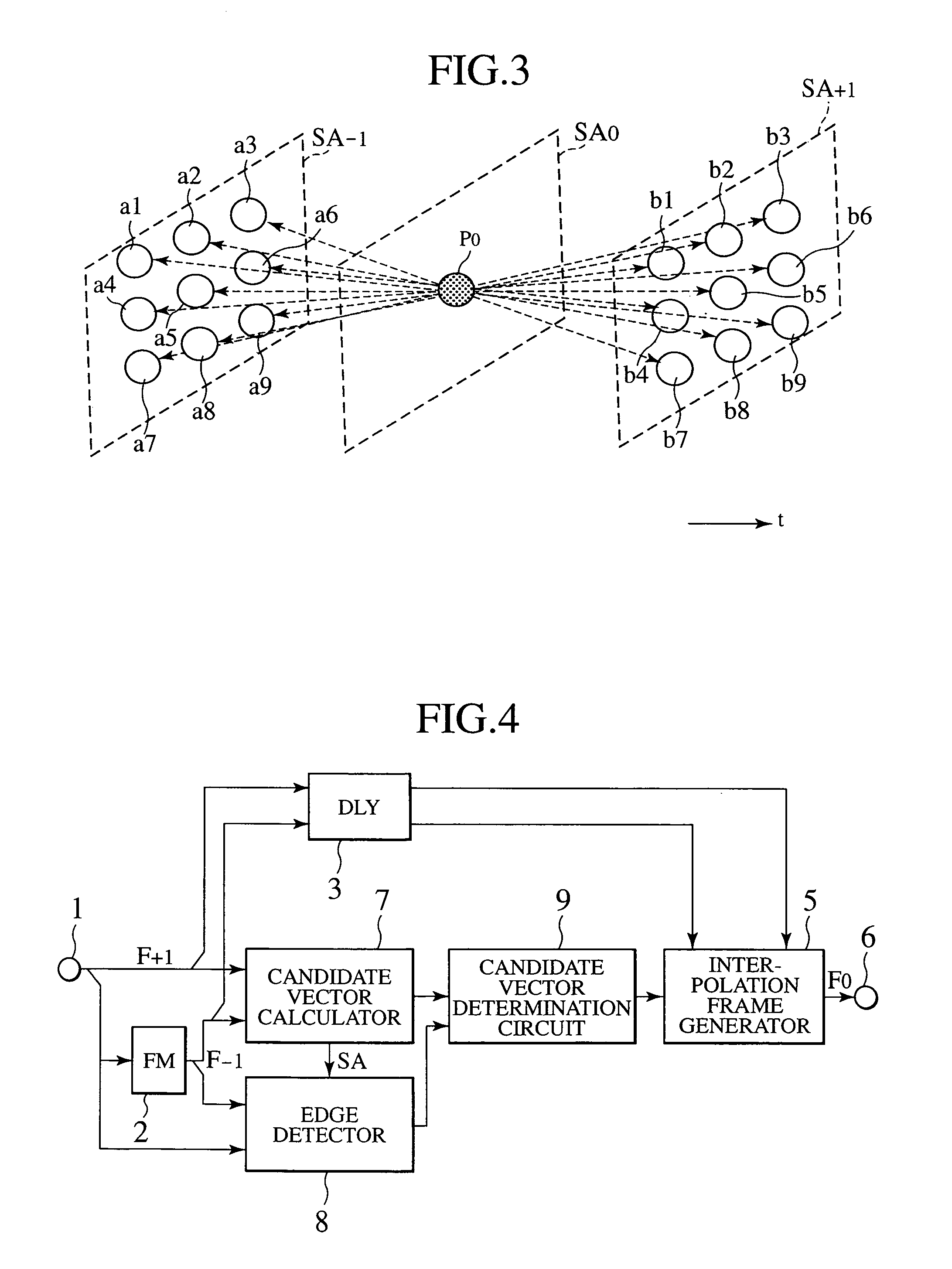
[0076]FIG. 4 is a block diagram showing an image interpolation device according to the present invention. Reference numeral 7 in FIG. 4 denotes a candidate interpolation pixel vector calculator, 8 an edge detector, and 9 an interpolation pixel vector determination circuit. Also, a section equivalent to that of FIG. 1 is assigned the same reference numeral in order to omit description.

[0077]For the first embodiment shown in FIG. 1, pixel pairs are calculated by the minimum differential pair calculator 4, then one specific pixel pair whose absolute differential luminance value becomes a minimum is selected from the pixel pairs, and an interpolation pixel vector is generated. In the second embodiment, however, a plurality of pixel pairs are selected from calculated pixel pairs in normal ascending order of an absolute differential luminance value, then a specific pixel pair is further selected from the above-selected plurality of pixel pairs in accordance with edge information, and an i...

third embodiment

[0107]FIG. 9 is a block diagram showing an image interpolation device according to the present invention. Reference numeral 9a in FIG. 9 denotes a candidate interpolation pixel vector determination circuit, and 10 an interpolation direction histogram detector. Sections equivalent to those of FIG. 4 are each assigned the same reference numeral, and description of these sections is omitted to avoid duplicate description.

[0108]In the present third embodiment, an interpolation pixel vector to be used to generate an interpolation frame is selected by an interpolation frame generator 5 considering, in addition to other factors, a direction of moving an entire image screen by, for example, scrolling at a constant rate.

[0109]In the candidate interpolation pixel vector determination circuit 9a of FIG. 9, as in the second embodiment of FIG. 4, of all the X number of candidate interpolation pixel vectors selected by a candidate interpolation pixel vector calculator 7, only the interpolation pi...


PUM


Abstract

More accurate frame-rate conversion is carried out in a simpler circuit configuration. Search areas SA+1 and SA−1 in each of which the pixel facing the interpolation position P0 of a pixel in an interpolation frame is taken as a central pixel are set in the current frame and immediately previous frame of an image signal, a set of pixels point-symmetrical to the interpolation position P0 in each of the search areas SA+1 and SA−1 are defined as pixel pairs, and differential luminance values between the individual pixels in the pixel pairs are calculated for each pixel pair. Of all these pixel pairs, only that having the minimum absolute differential value is selected as interpolation pixel pair, an interpolation frame is generated from the current frame and the immediately previous frame on the basis of the interpolation pixel vector of that interpolation pixel pair.

Description

CLAIM OF PRIORITY[0001]The present application claims priority from Japanese application serial no. JP 2004-316051, filed on Oct. 29, 2004, the content of which is hereby incorporated by reference into this application.BACKGROUND OF THE INVENTION[0002]1. Field of the Invention[0003]The present invention relates to an image interpolation device for changing a frame rate of dynamic-image signals, especially, for conducting frame interpolations, and a frame rate converter and image display apparatus using the image interpolation device.[0004]2. Description of the Related Art[0005]Currently, there are a variety of specifications concerning image signals such as the video signals used for video media and for personal computers (PCs). In general, the image signals defined by the Video Electronics Standards Association (VESA) are widely known, and image formats as many as several types varying in frame rate are defined, even for the VESA standards signals. Unlike this, the kind of image fo...

Claims


Application Information

Patent Timeline
Patent Type & Authority Patents(United States)
IPC IPC(8): H04N7/01
CPCG06T3/4007H04N7/014G06T7/2033H04N7/0142G06T7/246
Inventor OGINO, MASAHIROIGARASHI, YOUICHITANAKA, YOSHINORI
Owner PANASONIC LIQUID CRYSTAL DISPLAY CO LTD
Why Eureka
Try Eureka