Optical time-division demultiplexing apparatus

a time-division demultiplexing and optical technology, applied in multiplex communication, optics, instruments, etc., can solve the problems of difficult electrically to make high-speed optical demultiplexing, complex configuration of optical networks, noise of target optical pulses, etc., and achieve accurate demultiplexing and good selectivity

Inactive Publication Date: 2009-09-08
FUJITSU LTD
View PDF17 Cites 0 Cited by
  • Summary
  • Abstract
  • Description
  • Claims
  • Application Information

AI Technical Summary

Benefits of technology

[0010]An object of the present invention is to provide an apparatus for implementing optical time-division demultiplexing for a high-speed ETDM / OTDM signal with simple and stable high performance.
[0012]According to the present invention, an optical pulse of a particular channel transmitted in predetermined cycles can be accurately demultiplexed from an optically time-division multiplexed signal light. Especially, when a spectrum of signal light is expanded, the ratio at which the spectrum expands is made to depend on the intensity of the peak of an optical pulse. Therefore, by extracting the spectrum of a demultiplexed optical pulse in a position where a spectrum of an optical pulse desired not to be demultiplexed does not reach, some of optical pulses of different channels are not mixed up as noise at the time of demultiplexing. As a result, demultiplexing having good selectivity can be performed.

Problems solved by technology

However, since an optical carrier of wavelengths the number of which is equal to the number of channels is required, configuration of an optical network becomes complex.
One of the major problems when an ETDM / OTDM signal is used is demultiplexing.
Such high-speed optical demultiplexing is difficult to be made electrically because of restrictions on the operation speed of electronics.
This causes noise to the target optical pulse.
Actually, however, it is difficult to generate an optical pulse of control light having such a small pulse width, and accordingly, an apparatus for generating such an optical pulse becomes complex and expensive.

Method used


Image

  • Optical time-division demultiplexing apparatus
  • Optical time-division demultiplexing apparatus
  • Optical time-division demultiplexing apparatus

Examples


Embodiment Construction

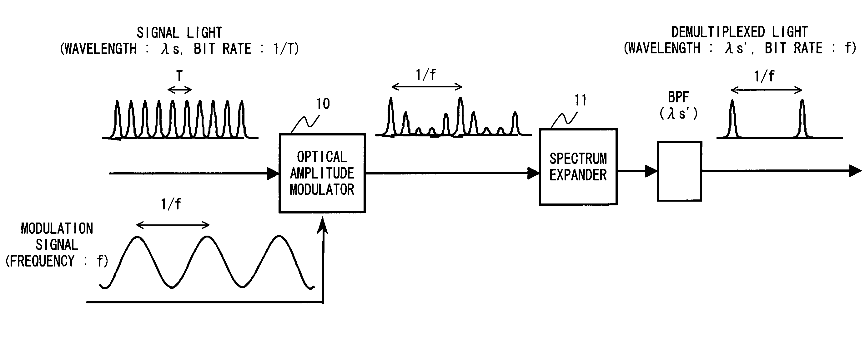
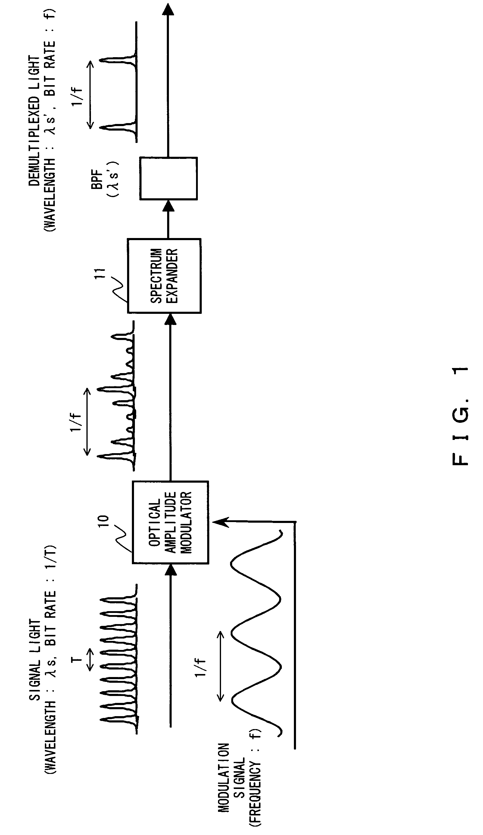
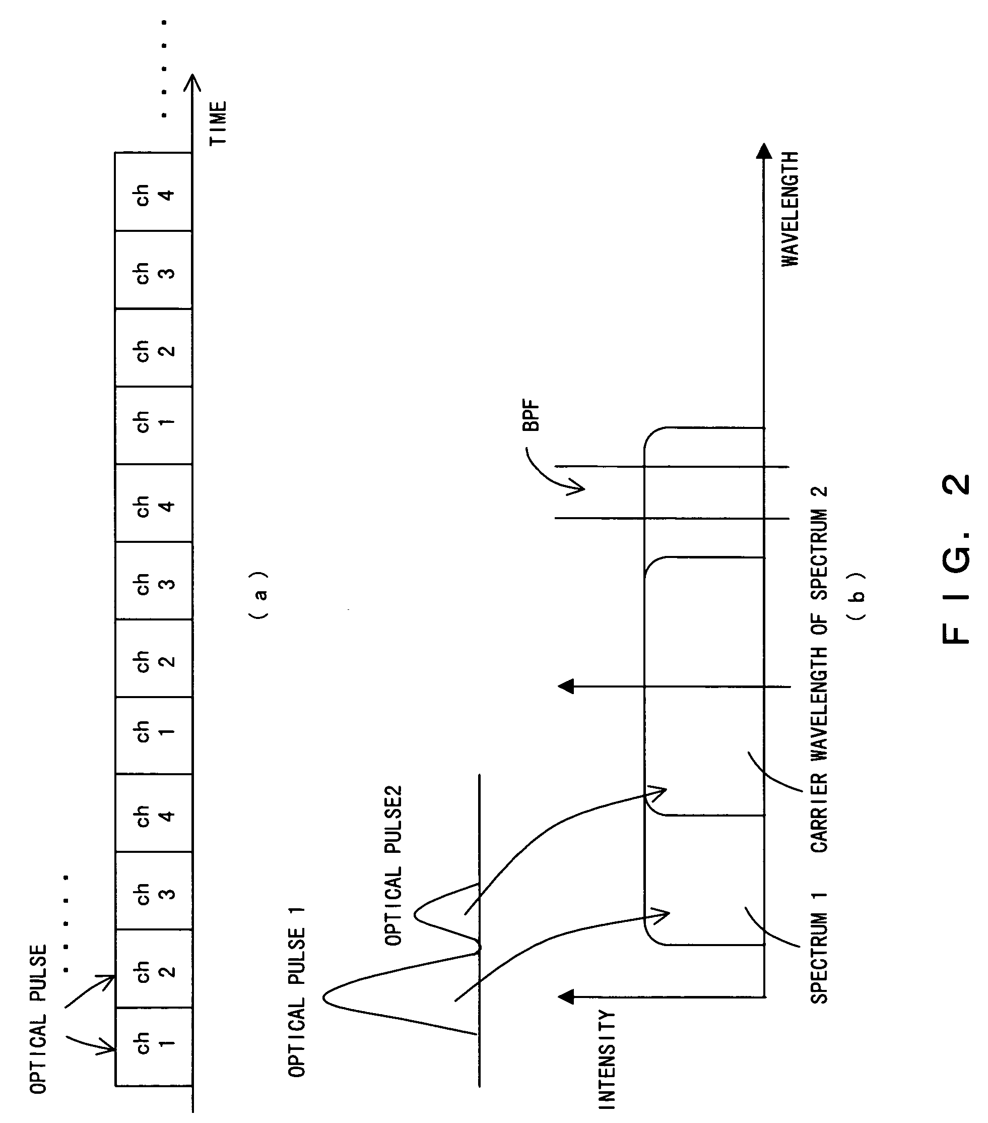
[0019]Preferred embodiments according to the present invention comprise the following functions.[0020](1) Amplitude-modulating a signal light with a repetitive signal of a reference frequency (10 GHz in the case of optical demultiplexing into 10 Gbit / s) for optical demultiplexing. At that time, matching the timing of the modulation signal with the pulse of a channel to be optically demultiplexed, and setting the amplitude of the channel to be optically demultiplexed to be larger than any other pulses. If possible, it is desirable that the peak power of an adjacent channel becomes almost half or lower than the peak power of the amplitude of the channel to be optically demultiplexed.[0021](2) After power-amplifying the amplitude-modulated signal light with an optical amplifier, inputting the signal light to an optical fiber, expanding its spectrum with self-phase modulation (SPM) that occurs within the fiber (generating a spectrum called supercontinuum), and extracting a component dif...


PUM

PropertyMeasurementUnit
frequencyaaaaaaaaaa
spectrumaaaaaaaaaa
self-phase modulationaaaaaaaaaa

Abstract

Amplitude modulation is performed for a signal light with a modulation signal having the same cycle as that of an optical pulse to be extracted by using an optical modulator. At this time, timing is adjusted so that the peak of the optical pulse of the channel to be extracted of the signal light becomes the largest. A spectrum of the amplitude-modulated signal light is expanded according to the size of the peak of the optical pulse by a spectrum expander. Then, part of the expanded spectrum is extracted with a band pass filter, whereby the optical pulse of the desired channel is extracted.

Description

BACKGROUND OF THE INVENTION[0001]1. Field of the Invention[0002]The present invention relates to an optical demultiplexing (DEMUX) apparatus for extracting a signal light of a reference rate, which configures a signal light multiplexed with electrical time-division multiplexing or optical time-division multiplexing (ETDM or OTDM).[0003]2. Description of the Related Art[0004]ETDM / OTDM are the promising multiplexing technologies for speeding up an optical network, and for increasing a capacity in terms of an implementation of an ultra-fast optical network in the future. Wavelength division multiplexing (WDM) is the most suitable multiplexing technology for a long-haul transmission. However, since an optical carrier of wavelengths the number of which is equal to the number of channels is required, configuration of an optical network becomes complex. Although the bit rate of an ETDM / OTDM signal becomes high at times equal to the number of channels, it can be transmitted over single opti...

Claims


Application Information

Patent Timeline
Patent Type & Authority Patents(United States)
IPC IPC(8): H04J14/08G02F1/025G02F1/035G02F1/35
CPCH04J14/08H04J14/083
Inventor WATANABE, SHIGEKI
Owner FUJITSU LTD
Why Eureka
Try Eureka