
Method of manufacturing an inkjet head

a manufacturing method and inkjet head technology, applied in the direction of piezoelectric/electrostrictive transducers, variable capacitors, inking apparatuses, etc., can solve the problems of increased manufacturing costs, increased manufacturing costs, and uneven thickness of the adhesion layer on the adhesion surface in the second adhesion step

Active Publication Date: 2009-09-15
BROTHER KOGYO KK
View PDF11 Cites 0 Cited by
  • Summary
  • Abstract
  • Description
  • Claims
  • Application Information

AI Technical Summary

Benefits of technology

The present invention provides a method of manufacturing an inkjet head that reduces manufacturing costs by simplifying the adhesion step and reducing the quantity of adhesive used. The method also ensures accurate positioning of the communication holes in the plates, preventing unintended stepped portions that can affect ink flow. The method involves laminating the plates together with thermosetting adhesive and applying pressure to the laminated plates in the plate-laminating-direction while heating them. The laminated plates constitute the ink passage unit, and the communication holes formed in each plate are overlaid to form the individual ink passage and nozzle. The method also allows for easy inspection of the communication holes. Overall, the method simplifies the manufacturing process and reduces manufacturing costs for the inkjet head.

Problems solved by technology

When the second adhesion step is performed in this case, the thickness of the adhesion layer on the adhesion surface in the second adhesion step may not be uniform.
When a large quantity of adhesive is used, manufacturing costs will increase.
In addition, manufacturing costs will increase due to the need for two adhesion steps.
When the plates in which the communication holes were formed are laminated together, the communication holes in adjacent plates may not be correctly positioned.
There is a possibility that unintended stepped portions will be formed inside the individual ink passage at the contact surfaces of adjacent plates.
When unintended stepped portions are produced inside the individual ink passages, the ink will not flow smoothly.

Method used


Image

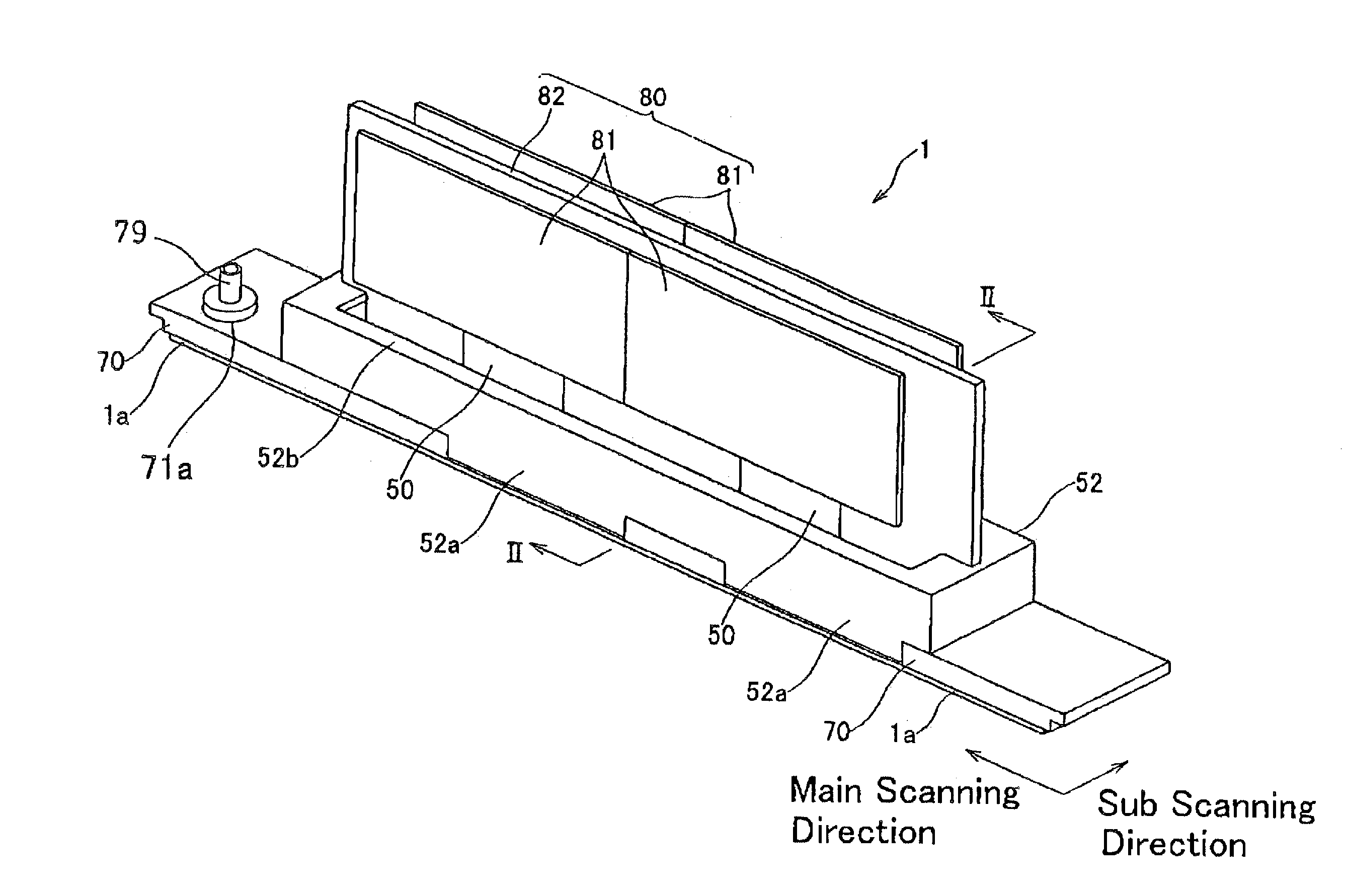
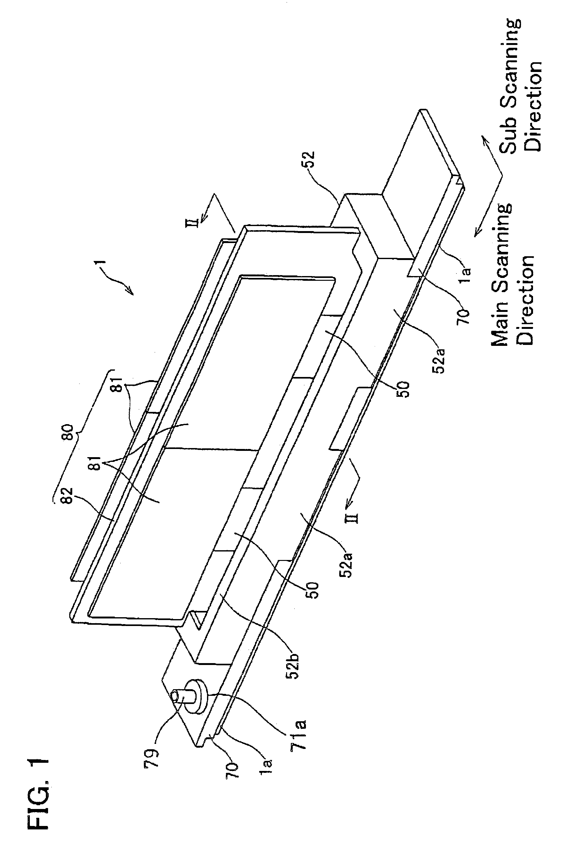
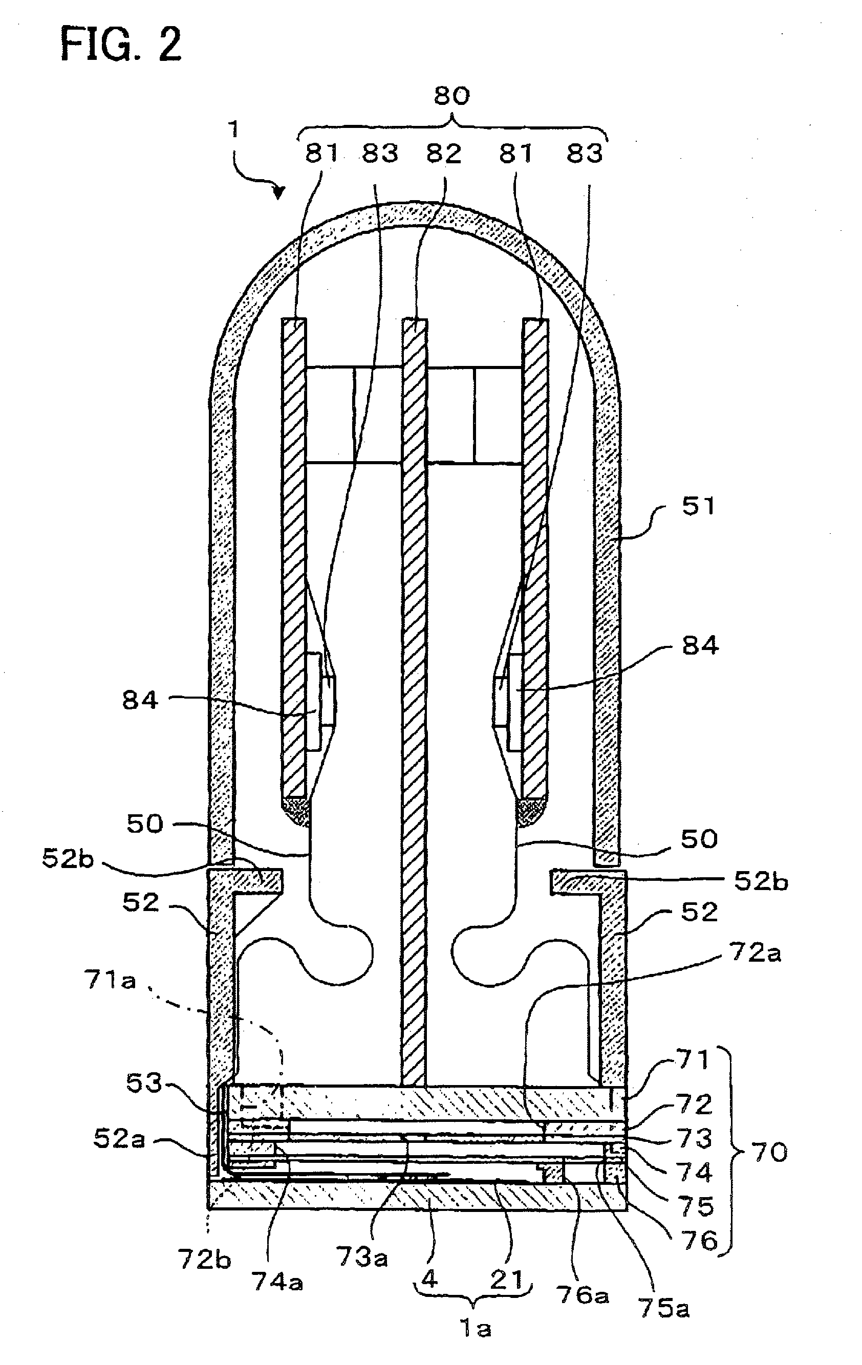
  • Method of manufacturing an inkjet head
  • Method of manufacturing an inkjet head
  • Method of manufacturing an inkjet head

Examples


Embodiment Construction

[0052]Preferable technical features of the invention are described below.

[0053]The inkjet head may have an actuator unit. It is preferred that the manufacturing method also has a step of laminating the actuator units with thermosetting adhesive onto the laminated plates. The actuator unit may be laminated so as to cover the communication hole formed in one of the plates that faces the actuator unit. The actuator unit laminating step is performed before the adhering step.

[0054]In the adhering step, the actuator unit and the laminated plates may be adhered simultaneously by applying pressure to the actuator unit and the laminated plates in the plate-laminating-direction while heating the actuator unit and the laminated plates.

[0055]Due to the aforementioned technical features, an inkjet head can be manufactured at an even lower cost by simultaneously adhering the laminated plates together with the actuator unit.

[0056]The actuator unit in the inkjet head may have a piezoelectric film, ...


PUM

PropertyMeasurementUnit
diameteraaaaaaaaaa
pressureaaaaaaaaaa
piezoelectricaaaaaaaaaa

Abstract

A method of manufacturing an inkjet head at a low cost is provided. The inkjet head has a passage unit. A plurality of plates are laminated together to form the passage unit. The passage unit has individual ink passages that extend in the plate laminating direction. When the passage unit is to be manufactured, communication holes that will become individual ink passages later will first be formed in the plurality of plates that form the passage unit. All of the plates in which the communication holes are formed will be laminated together with a thermosetting adhesive. The laminated plates will be heated and pressure will be applied thereto. In this way, all of the plates will be simultaneously adhered. An ink passage unit can be manufactured in one adhesion step. The manufacturing costs of the ink passage unit can be reduced. Components such as actuator units, an ink supply unit, and the like will be attached to the manufactured ink passage unit to complete an inkjet head. An inkjet head can be manufactured at a low cost.

Description

CROSS REFERENCE TO RELATED APPLICATION[0001]This application claims priority to Japanese Patent Application No. 2005-083057 filed on Mar. 23, 2005, the contents of which are hereby incorporated by reference into the present application.BACKGROUND OF THE INVENTION[0002]1. Field of the Invention[0003]The present invention relates to a method of manufacturing an inkjet head.[0004]2. Description of the Related Art[0005]An inkjet bead having an ink passage unit is known. An ink passage unit is formed by stacking (laminating) a plurality of plates together. Individual ink passages and nozzles are formed in the ink passage unit. The individual ink passages pass through the laminated plates in the direction of lamination. The direction of laminating is referred to as the plate-laminating-direction hereinafter. Nozzles are formed in the end portions of the individual ink passages. That it to say, the nozzles is formed in the outermost plate of the ink passage unit. The plate laminated on the...

Claims


Application Information

Patent Timeline
Patent Type & Authority Patents(United States)
IPC IPC(8): B23P17/00B41J2/14
CPCB41J2/1609B41J2/1623B41J2002/14217B41J2002/14225Y10T29/49401B41J2002/14459B41J2202/20Y10T29/42Y10T29/435B41J2002/14306
Inventor TERAKURA, TATSUO
Owner BROTHER KOGYO KK
Learn More