Fuel cell stack structure
a fuel cell and stack structure technology, applied in the field of fuel cell stack structure, to achieve the effect of reducing the voltage drop
- Summary
- Abstract
- Description
- Claims
- Application Information
AI Technical Summary
Benefits of technology
Problems solved by technology
Method used
Image
Examples
Embodiment Construction
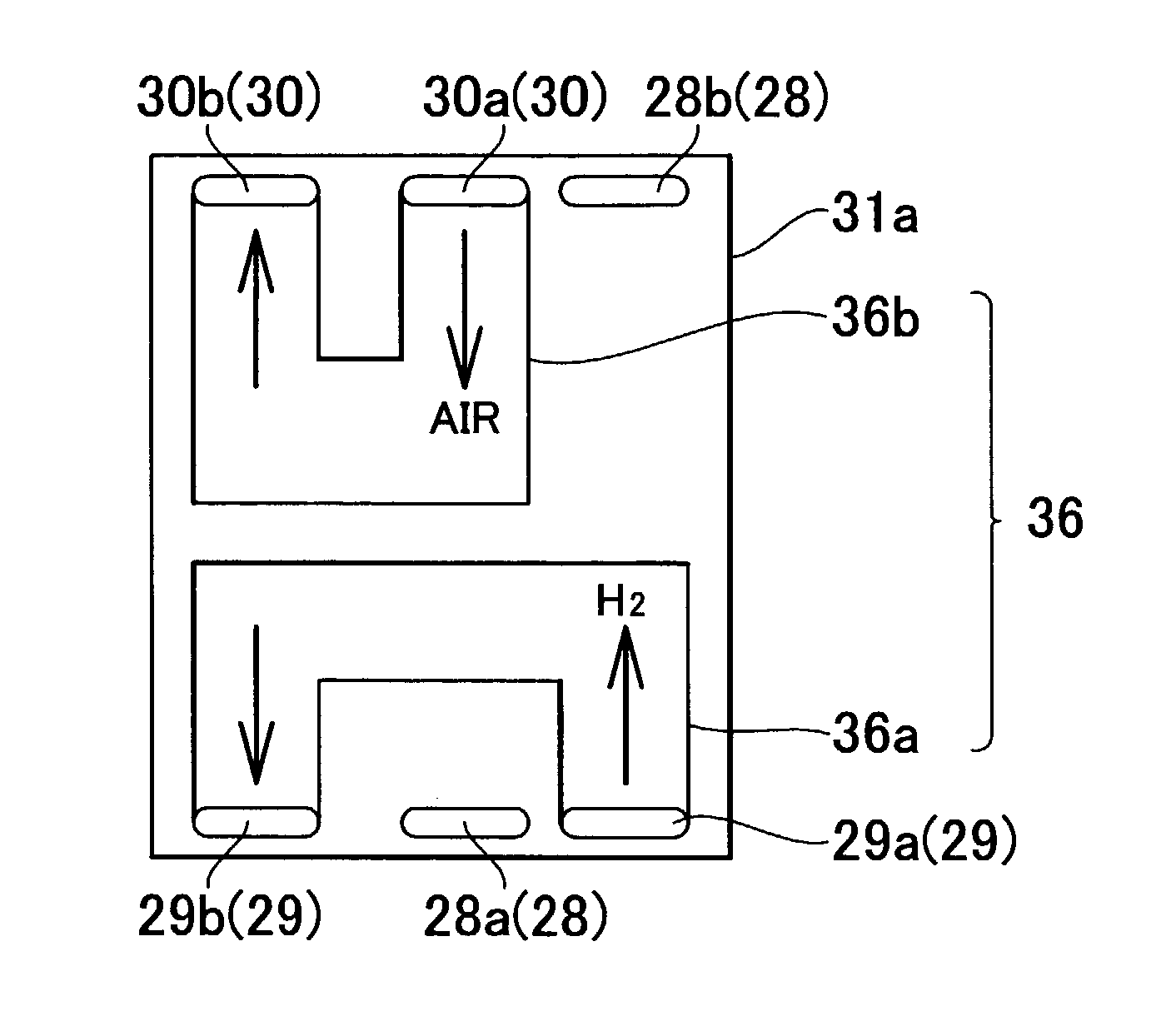
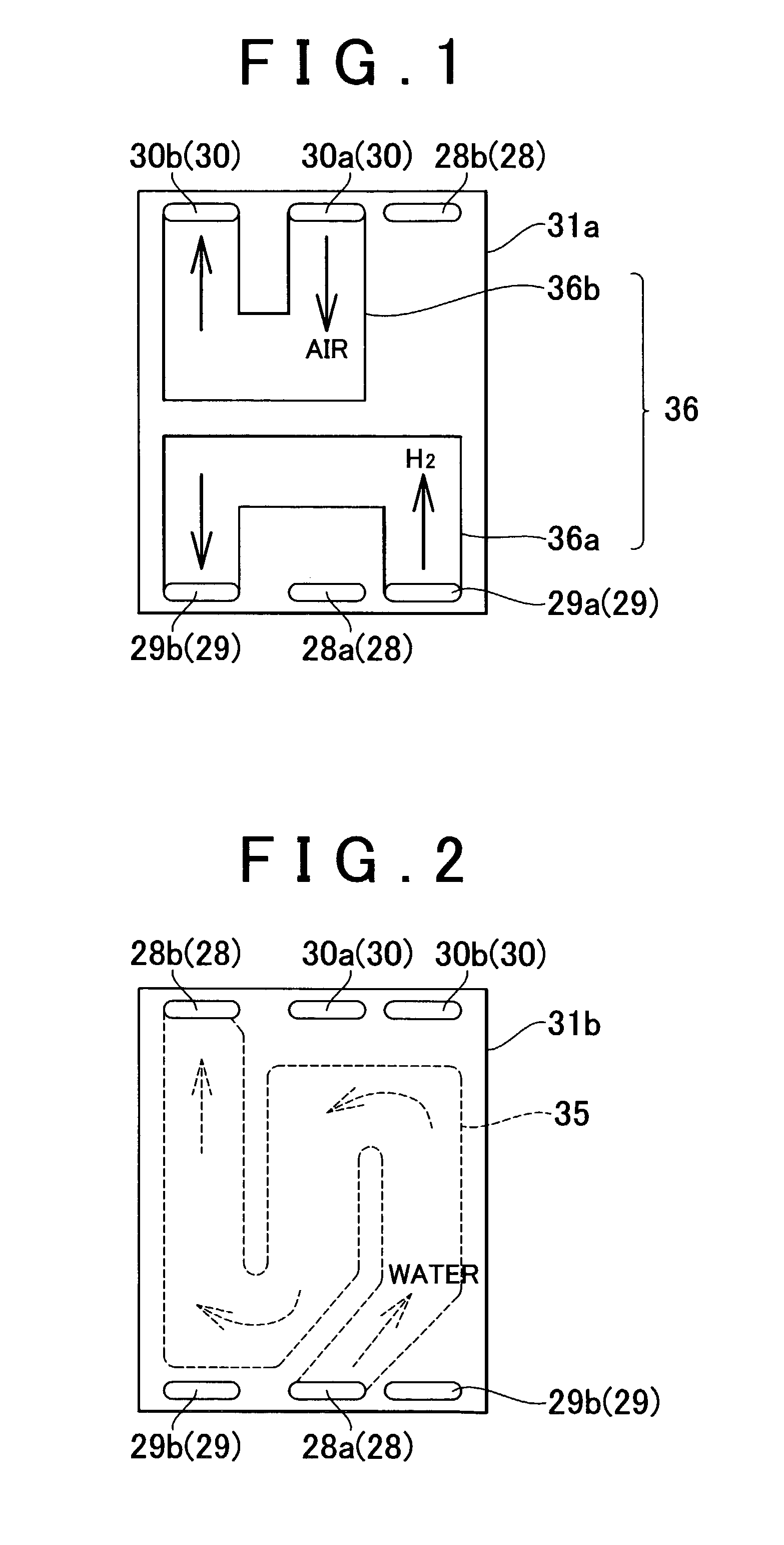
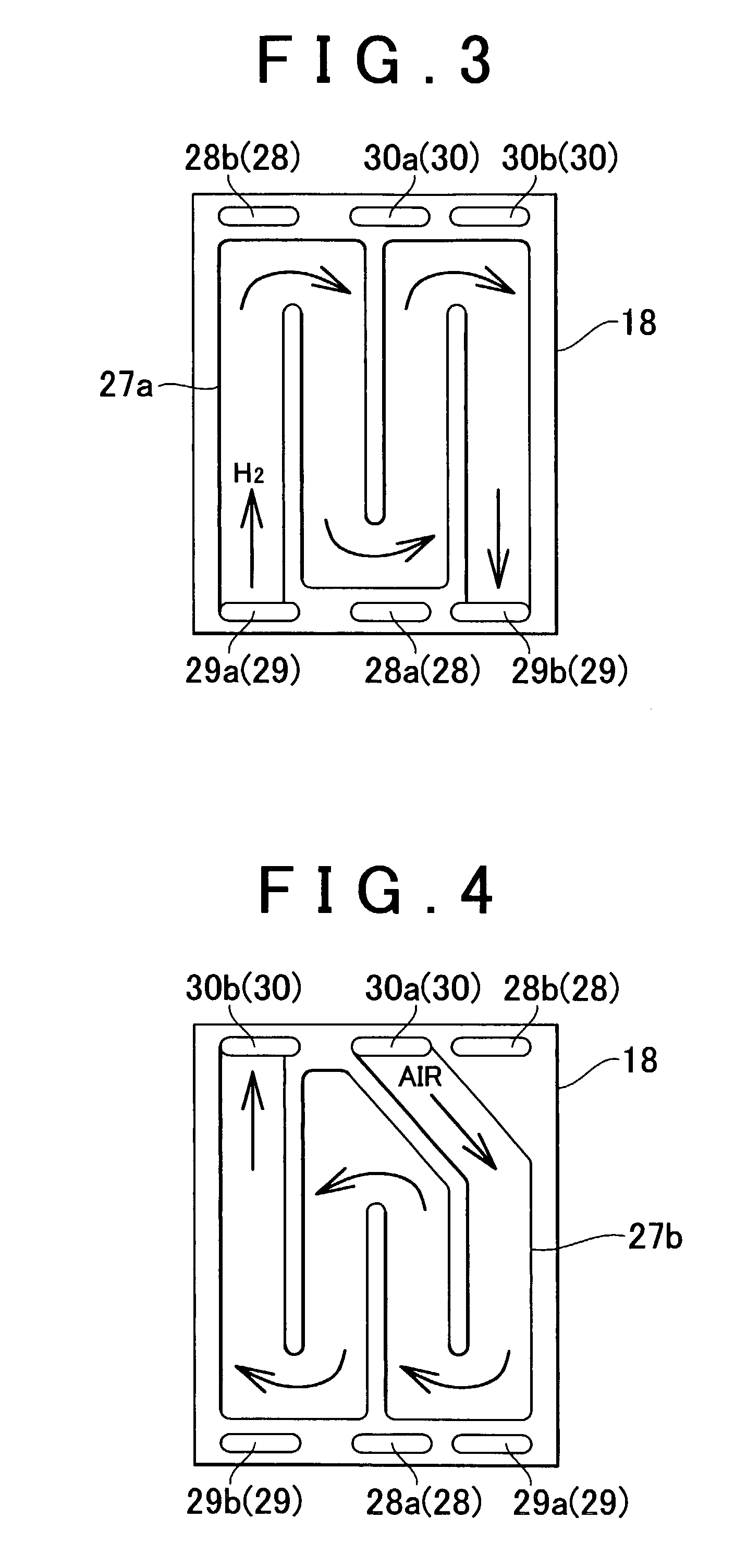
[0028]The fuel cell stack structure of the invention will be described hereinafter with reference to FIGS. 1 to 7.
[0029]One example of fuel cells to which gas flow channels in accordance with the invention are applied is a solid-polyelectrolyte fuel cell 10. The fuel cell 10 is mounted, for example, in a fuel cell powered vehicle. It is also appropriate, however, that the fuel cell be mounted in a non-vehicular object.
[0030]As is apparent from FIGS. 6 and 7, the solid-polyelectrolyte fuel cell 10 is constructed of a laminated body that is composed of membrane-electrode assemblies (MEA's) and separators. Each of the MEA's is composed of an electrolytic membrane 11 made of an ion exchange membrane, an electrode 14 (anode or fuel pole) made of a catalytic layer 12 and a diffusion layer 13, and an electrode 17 (cathode or air pole) made of a catalytic layer 15 and a diffusion layer 16. The catalytic layer 12 is disposed on one face of the electrolytic membrane 11, while the catalytic la...
PUM
| Property | Measurement | Unit |
|---|---|---|
| conductive | aaaaa | aaaaa |
| voltage | aaaaa | aaaaa |
| voltages | aaaaa | aaaaa |
Abstract
Description
Claims
Application Information
 - R&D
- Intellectual Property
- Life Sciences
- Materials
- Tech Scout
- Unparalleled Data Quality
- Higher Quality Content
- 60% Fewer Hallucinations
Browse by: Latest US Patents, China's latest patents, Technical Efficacy Thesaurus, Application Domain, Technology Topic, Popular Technical Reports.
© 2025 PatSnap. All rights reserved.Legal|Privacy policy|Modern Slavery Act Transparency Statement|Sitemap|About US| Contact US: help@patsnap.com


