Molded lens

a lens and micro-lens technology, applied in the field of lenses, can solve the problems of difficult to satisfactoryly transfer the surface profile of the mold, easy burr, and difficult to achieve good optical performance, and achieve the effect of reducing the diameter of the lens surface and good optical performan

Inactive Publication Date: 2009-09-15
FUJI PHOTO OPTICAL CO LTD
View PDF8 Cites 1 Cited by
  • Summary
  • Abstract
  • Description
  • Claims
  • Application Information

AI Technical Summary

Benefits of technology

[0015]The invention has been in view of the above circumstances, and provides a molded lens capable of attaining reduction in diameter of a lens surface even in a lens having very small diameter while maintaining good optical performances in a peripheral portion of a lens effective area.
[0028]In the molded lens described above, the outer diameter d1 (d1′) of the lens surface is formed at least 0.04 mm larger than the effective aperture d0 (d0′) of the lens surface. This numerical value of 0.04 mm was obtained from various investigated results made by the inventors. When the outer diameter d1 (d1′) of the lens surface is set larger than the effective aperture d0 (d0′) of the lens surface at least by 0.04 mm, deterioration in optical performances in the effective area, especially in the peripheral portion, of the lens surface can be prevented.

Problems solved by technology

However, in the periphery of a lens surface, a molding pressure is hard to apply and thus it is difficult to satisfactory transfer the surface profile of the mold.
On the contrary, when a molding pressure is increased such that a sufficient pressure is applied to the periphery of the lens surface, burr occurs easily.
Also, when a mold clamping force is increased to prevent an occurrence of the burr, it is hard for air to come out of the mold.
As a result, a surface of the mold may not be transferred.
In such micro lens, it is difficult to utilize JP 2001-341134 A. Also, even though JP 2001-341134 A is used, it is difficult to improve transferability in the peripheral portion of the mold without fail.
As a result, unless an effective aperture of the lens surface is set considerably smaller than an outer diameter of the lens surface, a desired refracting action cannot be exerted on rays passing through the peripheral portion of the lens.
Conversely, in order to ensure the effective aperture of the lens surface having a predetermined size, the diameter of the lens surface is set large, which conflicts with the above demand for size reduction.
In this event, such problem arises in not only the molded lens manufactured by the injection molding method but also molded lens manufactured by the compression molding method.

Method used


Image

  • Molded lens
  • Molded lens
  • Molded lens

Examples


example 1

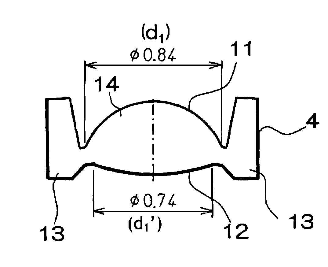
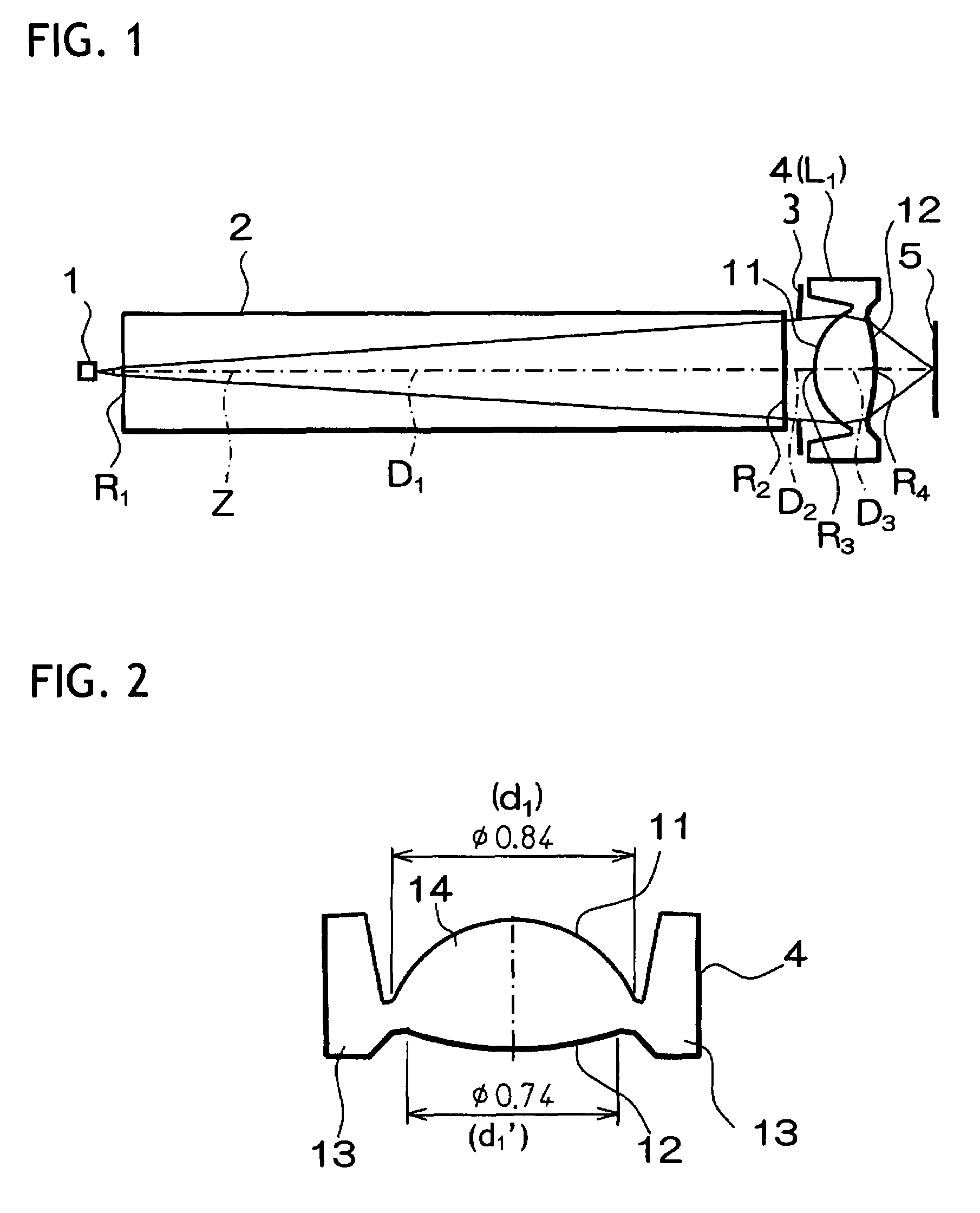
[0056]The molded lens according to Example 1 of the invention was formed by molding plastic material using the injection molding mold. As shown in FIG. 1, this molded lens was formed of a single lens L1, and also a surface of the lens L1 on the light source side (third surface) and a surface of the lens L1 on the image surface side (fourth surface) were formed into an aspheric shape.

[0057]Here, these aspheric surfaces are given by following aspheric formula.

[0058]Z=C·Y21+1-K·C2·Y2+A2⁢Y4+A3⁢Y6+A4⁢Y8+A5⁢Y10(4)

Where[0059]Z: a length of perpendicular from a point on an aspheric surface at a height Y from an optical axis to a tangent plane (a plane perpendicular to the optical axis) of an aspheric vertex[0060]C: reciprocal of a radius of curvature R of the aspheric surface near the optical axis[0061]Y: height from the optical axis[0062]K: eccentricity[0063]A2, A3, A4, A5: fourth, sixth, eighth, and tenth-order aspheric coefficients

[0064]Also, respective numerical values concerning the op...

example 2

[0073]Like Example 1, the molded lens according to Example 2 of the invention was formed by molding the plastic material using the injection molding mold. As shown in FIG. 5, this molded lens was formed of a single lens 4, and also a surface of the lens 4 on the light source side (first surface) and a surface of the lens 4 on the image surface side (second surface) were formed into the aspheric shape. Here, reference symbols in FIG. 5 correspond to those of Example 1 shown in FIG. 2 (this is also true of Example 3 in FIG. 8).

[0074]Here, these aspheric surfaces are given by above aspheric formula.

[0075]Also, respective numerical values concerning the molded lens 4 according to this Example 2 are shown in the following table 3.

[0076]In the middle stage of the table 3, a radius of curvature R (mm) of each optical surface, a surface separation D (mm) on the optical axis Z, and a refractive index N in the used wavelength of each lens are given. Here, the numbers in this stage denote the ...

example 3

[0083]FIG. 7 is a view showing the configuration of an optical system of an optical recording device using a molded lens according to Example 3 of the invention. FIG. 8 is an enlarged view showing the molded lens according to Example 3.

[0084]The device shown in FIG. 7 is constructed substantially similarly to the configuration of the optical system of the optical recording device using the molded lens according to the above Example 1 shown in FIG. 1. Therefore, the same reference symbols are assigned to the respective portions corresponding to those in FIG. 1, and their detailed explanation will be omitted herein.

[0085]The molded lens according to Example 3 of the invention was formed by molding a glass material using the compression molding mold. As shown in FIG. 7, this molded lens was formed of a single lens L1, and also a surface of the lens L1 on the light source side (third surface) and a surface of the lens L1 on the image surface side (fourth surface) were formed into an asp...


PUM


Abstract

A laser beam output from a semiconductor laser light source 1 is transmitted through a cover glass 2 in the optical axis Z direction, is incident on a molded lens 4 in a state of divergent rays, is converted into convergent rays by the molded lens 4, and is applied onto a recording face 5 of the optical recording medium. A diaphragm 3 is arranged. An area of each lens surface onto which a luminous flux of the laser beam restricted by the diaphragm 3 is applied corresponds to an effective area. The following expression (1) is satisfied:d1−d0≧0.04 mm  (1)where d0 denotes an effective aperture of one of the lens surfaces, andd1 denotes an outer diameter of the one of the lens surfaces.

Description

CROSS-REFERENCE TO RELATED APPLICATIONS[0001]This application is based upon and claims the benefit of priority from the Japanese Patent Application No. 2006-197588 filed on Jul. 20, 2006; the entire contents of which are incorporated herein by reference.BACKGROUND OF THE INVENTION[0002]1. Technical Field[0003]The invention relates to a lens manufactured by the mold molding and, more particularly, a molded lens having micro lens diameter such as an imaging lens for a mobile terminal, a recording / reproducing lens for an optical disk, a projecting / receiving lens for optical communication and an objective lens for an endoscope.[0004]2. Description of the Related Art[0005]In recent years, the molded lens is utilized in various uses at the request of weight reduction and cost reduction.[0006]For example, in the case where the molded lens is formed by the injection molding, the molded lens is formed by a series of the following operation processes. That is, plastic material is softened by ...

Claims


Application Information

Patent Timeline
Patent Type & Authority Patents(United States)
IPC IPC(8): G02B13/18
CPCG02B3/04G11B7/1374G11B7/1353G02B13/0025G02B1/041
Inventor KATSUMA, TOSHIAKIMORI, MASAOKITAHARA, YUORI, TETSUYA
Owner FUJI PHOTO OPTICAL CO LTD
Why Eureka
Try Eureka