Clip detection in PWM amplifier

a technology of amplifiers and clips, applied in the direction of digital/coded signal control, instruments, code conversion, etc., can solve the problems of low performance applications, complex and costly applications to implement, and the solution is not widely accepted, and achieves the effect of stable feedback signals

Inactive Publication Date: 2009-09-15
INTERSIL INC
View PDF16 Cites 10 Cited by
  • Summary
  • Abstract
  • Description
  • Claims
  • Application Information

AI Technical Summary

Benefits of technology

[0013]In one embodiment, the system also includes a filter for filtering the output of the detector before this information is provided to the signal processor as feedback. The filtering of the feedback may serve to prevent the signal processor from modifying the audio signal if the clipping of the audio signal occurs only occasionally, while allowing the signal processor to modify the audio signal if the clipping of the audio signal occurs more frequently. In one embodiment, the system also includes a flag circuit coupled between the filter and the signal processor. The flag circuit is configured to receive the filtered feedback signal from the filter and to assert an output signal that is provided to the signal processor when the filtered feedback signal is asserted. The output signal produced by the flag circuit remains asserted until the signal processor resets the flag circuit. This provides an even more stable feedback signal to the signal processor than simply filtering the signal.

Problems solved by technology

More particularly, these attempts utilized analog modulation schemes that resulted in very low performance applications.
These applications were very complex and costly to implement.
Consequently, these solutions were not widely accepted.
Prior art analog implementations of Class D technology have therefore been unable to displace legacy Class AB amplifiers in mainstream amplifier applications.
These digital PWM schemes, however, do little to offset the major barriers to integration of PWM modulators into total amplifier solutions.
Class D technology has therefore continued to be unable to displace legacy Class AB amplifiers in mainstream applications.
One of the problems that exists in current PWM amplifier systems is that the processing of audio signals cannot be easily controlled to achieve optimal performance.
This distorts the audio signal represented by the data and produces audio artifacts that can be audible.
The clipping of the signal received by quantizer 210 also results in quantization error.
The quantization error can produce instability in the noise shaper, as well as other undesirable audible effects.
While this does relieve the problem of quantization error that would otherwise occur as a result of clipping by the quantizer, it does not eliminate the distortion of the signal from clipping, and may even aggravate the problem, since the clipping circuit clips the signal at lower levels than the quantizer.
Put another way, the use of the clipping circuit has the undesirable effect of limiting the maximum range of the output (the modulation index) more than is strictly necessary.

Method used


Image

  • Clip detection in PWM amplifier
  • Clip detection in PWM amplifier
  • Clip detection in PWM amplifier

Examples


Embodiment Construction

[0025]One or more embodiments of the invention are described below. It should be noted that these and any other embodiments described below are exemplary and are intended to be illustrative of the invention rather than limiting.

[0026]As described herein, various embodiments of the invention comprise systems and methods for detecting clipping conditions in an audio signal and processing the signal to reduce the clipping conditions.

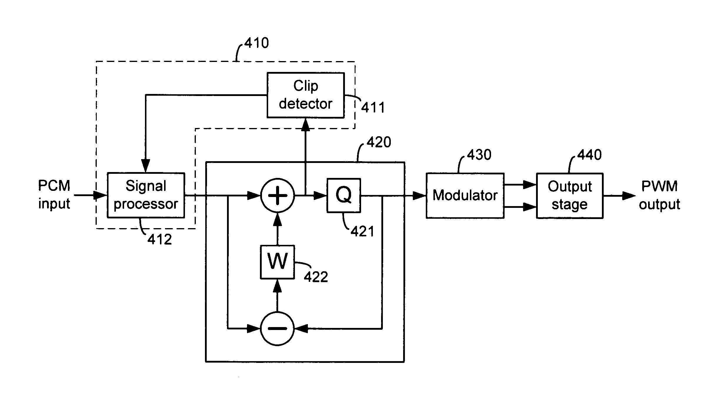
[0027]One embodiment of the invention comprises a system for reducing some of the problems of prior art systems, where, instead of clipping the input audio signal at a fixed level, the input audio signal is processed in a variable manner. For instance, at some times, the input audio signal may be clipped, at other times the input audio signal may be compressed, and at still other times the input audio signal may not be modified at all. In one embodiment, the system includes a noise shaper, a modulator, an output stage and several additional components. Thes...


PUM


Abstract

Systems and methods for detecting clipping conditions in an audio signal and processing the signal to reduce the clipping conditions. In one embodiment, a system comprises a noise shaper, a modulator, an output stage and other components. A detector detects clipping in the noise shaper and a signal processor processes the audio signal input to the noise shaper based on feedback received from the detector. The signal processor may function to modify the input audio signal in different ways in response to different conditions that are detected by the detector. A filter may be included to filter the output of the detector before being provided to the signal processor. A flag circuit may be coupled between the filter and the signal processor to assert an output signal until the signal processor resets the flag circuit.

Description

RELATED APPLICATIONS[0001]This application claims priority to U.S. Provisional Patent Application No. 60 / 469,770, entitled “Clip Detection in PWM Amplifier”, by Andersen, et al., filed May 12, 2003; U.S. Provisional Patent Application No. 60 / 456,414, entitled “Adaptive Anti-Clipping Protection,” by Taylor, et al., filed Mar. 21, 2003; U.S. Provisional Patent Application No. 60 / 456,430, entitled “Frequency Response Correction,” by Taylor, et al., filed Mar. 21, 2003; U.S. Provisional Patent Application No. 60 / 456,429, entitled “High-Efficiency, High-Performance Sample Rate Converter,” by Andersen, et al., filed Mar. 21, 2003; U.S. Provisional Patent Application No. 60 / 456,421, entitled “Output Device Switch Timing Correction,” by Taylor, et al., filed Mar. 21, 2003; U.S. Provisional Patent Application No. 60 / 456,422, entitled “Output Filter, Phase / Timing Correction,” by Taylor, et al., filed Mar. 21, 2003; U.S. Provisional Patent Application No. 60 / 456,428, entitled “Output Filter Sp...

Claims


Application Information

Patent Timeline
Patent Type & Authority Patents(United States)
IPC IPC(8): H03G7/00G06F17/00H04B15/00H03F1/52H03F3/217H03G3/00H03M3/00H04L7/02
CPCH03F1/523H03F3/2171H04L7/005H03G7/007H03M3/48H04L7/02H03G3/002H03F2200/331H03F2200/66
Inventor ANDERSEN, JACK B.HAND, LARRY E.TAYLOR, WILSON E.
Owner INTERSIL INC
Why Eureka
Try Eureka