Highly sensitive AMR bridge for gear tooth sensor

a gear tooth sensor, high-sensitivity technology, applied in the direction of instruments, galvano-magnetic devices, magnetic field measurement using galvano-magnetic devices, etc., can solve the problems of complex and expensive permanent magnet design

Inactive Publication Date: 2009-09-22
HEADWAY TECH INC
View PDF11 Cites 48 Cited by
  • Summary
  • Abstract
  • Description
  • Claims
  • Application Information

AI Technical Summary

Benefits of technology

[0016]Still another object of at least one embodiment of the present invent

Problems solved by technology

In this approach, the permanent magnet d

Method used


Image

  • Highly sensitive AMR bridge for gear tooth sensor
  • Highly sensitive AMR bridge for gear tooth sensor
  • Highly sensitive AMR bridge for gear tooth sensor

Examples


Embodiment Construction

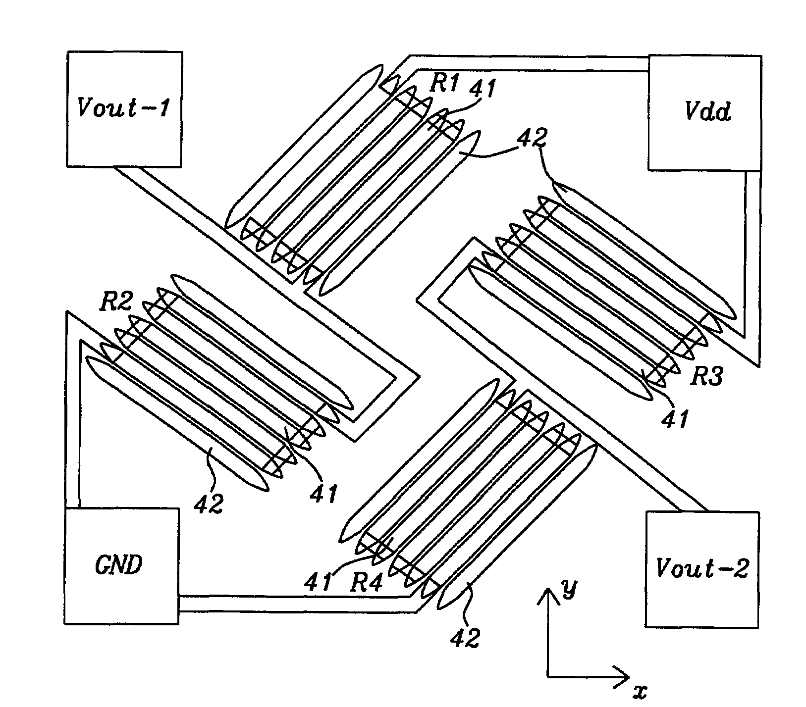
[0026]In the sensor of the present invention, four AMR sensing elements are arranged to form one Wheatstone bridge. These four AMR sensing elements have identical geometries and each is oriented to be at an angle of 45 degrees relative to its immediate neighbors, as shown in FIG. 4. Each AMR sensing element comprises several parallel AMR stripes. Each AMR stripe has been given the same width, which ranges from 5 to 50 microns. The gap (separation) between adjacent stripes is much smaller than each stripe's width, preferably less than 0.5 micron although a separation up to about 2 microns can be tolerated, if need be. Within each sensing element the AMR stripes are series connected through high conductance layers, thereby forming one of the four resistors of the Wheatstone bridge.

[0027]An additional AMR stripe is placed alongside the outermost sensing stripe of each resistor, also with a very small separation (or gap) that is preferably less than 0.5 micron, but which is not electric...


PUM


Abstract

An AMR gear tooth rotation sensor and a method for utilizing it are disclosed. These facilitate easy manufacture of the device without sacrificing either high sensitivity or high signal output. This is achieved by forming individual sensing elements out of AMR stripes and then connecting four such sensing elements as a Wheatstone bridge. The latter is attached to a permanent magnet that provides a bias field whose value rises and falls as wheel teeth and valleys (respectively) move past the rotation sensor.

Description

FIELD OF THE INVENTION[0001]The invention relates to the general field of rotation sensors with particular reference to gear wheels and magnetic sensors based on anisotropic magneto-resistance.BACKGROUND OF THE INVENTION[0002]Conventional gear tooth sensors [1] consist of a Hall effect sensor, and integrated circuit (IC) and a hard magnet, as shown in FIG. 1. The Hall IC supports two Hall sensors 12, which sense the magnetic profile of the ferromagnetic target simultaneously, but at different points, generating a differential internal analog voltage that is further processed for precise switching of the digital output signal. To achieve a high differential signal output, the two Hall probes (or sensors) are spaced so that one Hall sensor faces a field concentrating tooth and the other Hall sensor faces a gap between teeth.[0003]Permanent magnet 13 is mounted, with either pole being to the rear of IC 11, to provide a constant magnetic bias field. When one Hall sensor momentarily face...

Claims


Application Information

Patent Timeline
IPC IPC(8): G01B7/30G01R33/05G01R33/09
CPCB82Y25/00G01R33/096G01R33/093
Inventor GUO, YIMINGORMAN, GRACE
Owner HEADWAY TECH INC
Why Eureka
Try Eureka