
Magnetoresistive sensor for measuring a magnetic field

a magnetic field and sensor technology, applied in the direction of magnetic field-controlled resistors, magnetic measurements, instruments, etc., can solve the problems of insufficient development of high-sensitivity devices with sufficient yield for low-cost mass production, and insufficient sensitivity and/or dynamic range. , to achieve the effect of high linearity, low hysteresis, and high sensitivity

Active Publication Date: 2015-04-02
MULTIDIMENSION TECH CO LTD
View PDF7 Cites 32 Cited by
  • Summary
  • Abstract
  • Description
  • Claims
  • Application Information

AI Technical Summary

Benefits of technology

The patent text describes a method to make magnetic sensors that have high sensitivity and low hysteresis. The method uses standard semiconductor manufacturing technology to produce linear magnetic sensors with magnetic tunnel junction or giant magnetoresistance films. These sensors also have built-in permanent magnets to compensate for offset. The result is a high sensitivity magnetoresistor sensor with low drift, good linearity, and temperature stability. This makes it easier to use these sensors in practical applications.

Problems solved by technology

However, they all suffer from various limitations well known in the art, for example, excessive size, inadequate sensitivity and / or dynamic range, cost, reliability and other factors.
Although MTJ devices are compatible with standard semiconductor fabrication processes, methods for building high sensitivity devices with sufficient yield for low cost mass production have not been adequately developed.
In particular, yield issues due to offset in the magnetoresistive response of MTJ sensors, and difficulty in matching the magnetoresistive response of MTJ elements when combined to form bridge sensors have proven difficult.
These “biasing fields” have, in the past, required using external coils or permanent magnets that are undesirable from a power, cost, and size standpoint.

Method used


Image

  • Magnetoresistive sensor for measuring a magnetic field
  • Magnetoresistive sensor for measuring a magnetic field
  • Magnetoresistive sensor for measuring a magnetic field

Examples


Embodiment Construction

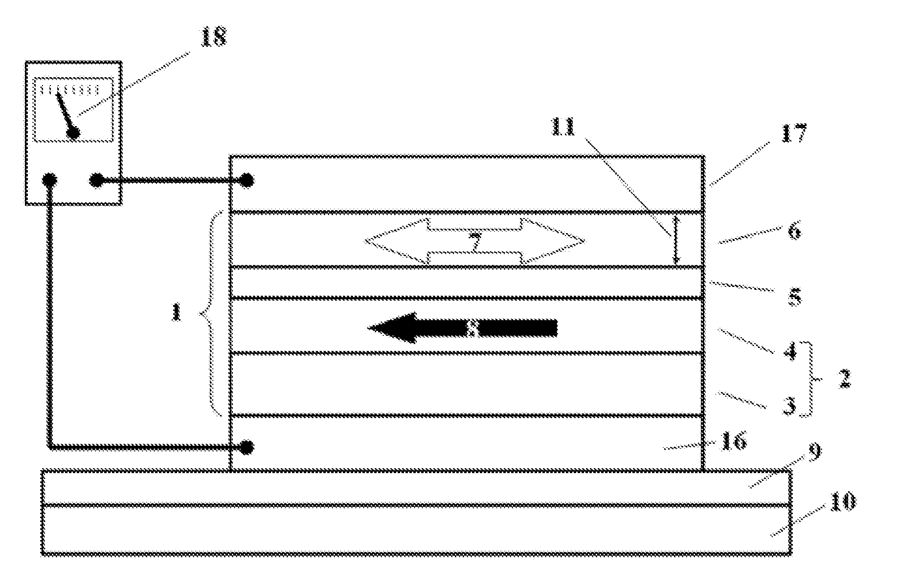
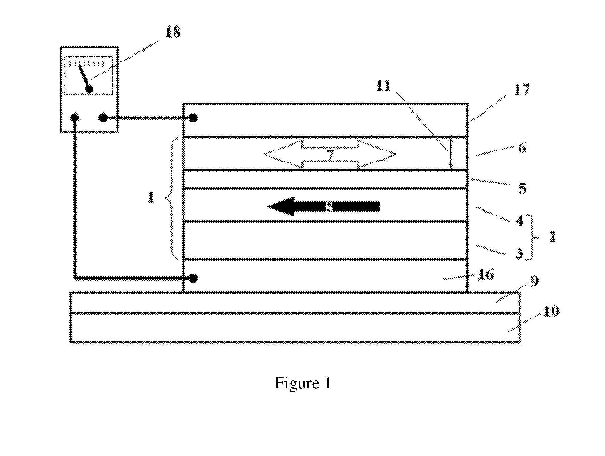
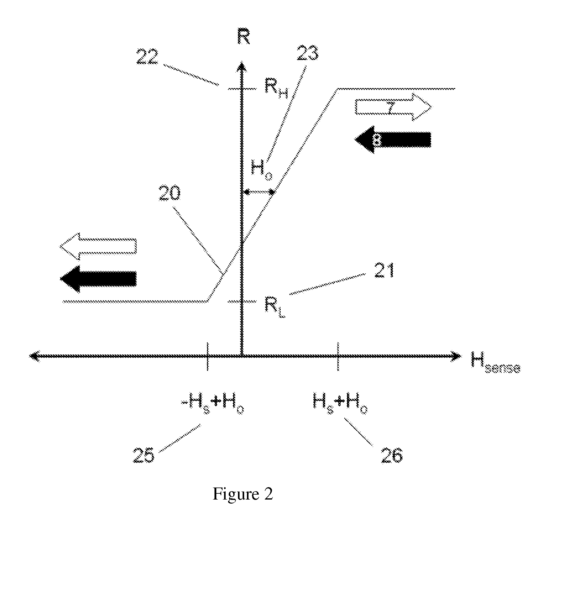
[0070]A schematic of the construction and electrical measurement of the resistance of a Magnetic Tunnel Junctions (MTJ) is shown in FIG. 1. MTJ stack, 1, consists of a ferromagnetic layer 4, and pinning layer 3, which can be an antiferromagnet; these are magnetically coupled together to form the pinned magnetic layer, 2. Tunnel barrier, 5, made of MgO or Al2O3; is formed directly on top of the ferromagnetic layer 4. The ferromagnetic layer, 6, is formed on top of barrier 5. The orientation of “pinned” layer magnetization vector, 8, and “sensing” layer magnetization vector, 7, are indicated by the direction of their arrows. The orientation of pinned layer magnetization vector 8 is designed to be relatively fixed in the presence of modest size magnetic fields. The orientation of sensing layer magnetization vector 7 is designed to be relatively “free” to rotate compared to that of the fixed layer. This rotational freedom is indicated by the double-ended arrow 7 in contrast to the singl...


PUM


Abstract

The present invention relates to a magnetoresistive sensor for measuring a magnetic field. A calculation of the sensitivity to external magnetic fields is provided, and it is shown to be related to the shape anisotropy of the magnetoresistive sensing elements. Moreover, it is shown that sensitivity may be made highest when the shape of the magnetoresistive element is long parallel to the sensing axis, and a magnetic bias field strong enough to saturate the magnetoresistive element's magnetization, Hcross, is applied perpendicular to the sensing axis. A monolithic permanent magnet is provided to generate the Hcross and it may be applied at an angle in order to counteract non-ideal fields along the sense axis direction. The high sensitivity magnetoresistive element can be used in many electrical form-factors. Six exemplary bridge configurations are described herein.

Description

CROSS-REFERENCE TO A RELATED APPLICATION[0001]This application is a 35 U.S.C. §371 national phase application of PCT / CN2013 / 071676, filed on Feb. 19, 2013, which claims priority to a Chinese Patent Application No. CN 20120037732.9, filed on Feb. 20, 2012, incorporated herein by reference in its entirety.FIELD OF THE INVENTION[0002]The invention relates to sensors for magnetic field detection, more specifically to magnetoresistive magnetic field sensors.BACKGROUND OF THE INVENTION[0003]Magnetic sensors are widely used in modern systems to measure or detect physical parameters including but not limited to magnetic field strength, current, position, motion, orientation, and so forth. There are many different types of sensors in the prior art for measuring magnetic field and other parameters. However, they all suffer from various limitations well known in the art, for example, excessive size, inadequate sensitivity and / or dynamic range, cost, reliability and other factors. Thus, there c...

Claims


Application Information

Patent Timeline
Patent Type & Authority Applications(United States)
IPC IPC(8): G01R33/09H01L43/08
CPCG01R33/093H01L43/08G01R33/098G01R15/205H10N50/10
Inventor DEAK, JAMES GEZAJIN, INSIKSHEN, WEIFENGXUE, SONGSHENG
Owner MULTIDIMENSION TECH CO LTD
Learn More