Liquid crystal phase shift unit and phased antenna composed of the same

A liquid crystal and liquid crystal layer technology, which is applied in the imaging and radar fields of terahertz electronics, can solve the problems of high difficulty in realization, high manufacturing cost, and increasing the distance between array elements, and achieve the effect of low processing difficulty and low cost

Active Publication Date: 2016-11-23
HEFEI UNIV OF TECH
View PDF7 Cites 29 Cited by
  • Summary
  • Abstract
  • Description
  • Claims
  • Application Information

AI Technical Summary

Problems solved by technology

Among them, the parasitic characteristics of varactor diodes in the high-frequency band are relatively serious, and can only be used in low-frequency bands; the phase shifting characteristics of ferrite phase shifters are easy to migrate with the external environment, and it is difficult to accurately control; MEMS phase shifters require precise processing However, the high phase shifter based on PIN diodes needs to occupy a large area

Method used


Image

  • Liquid crystal phase shift unit and phased antenna composed of the same
  • Liquid crystal phase shift unit and phased antenna composed of the same
  • Liquid crystal phase shift unit and phased antenna composed of the same

Examples


Embodiment Construction

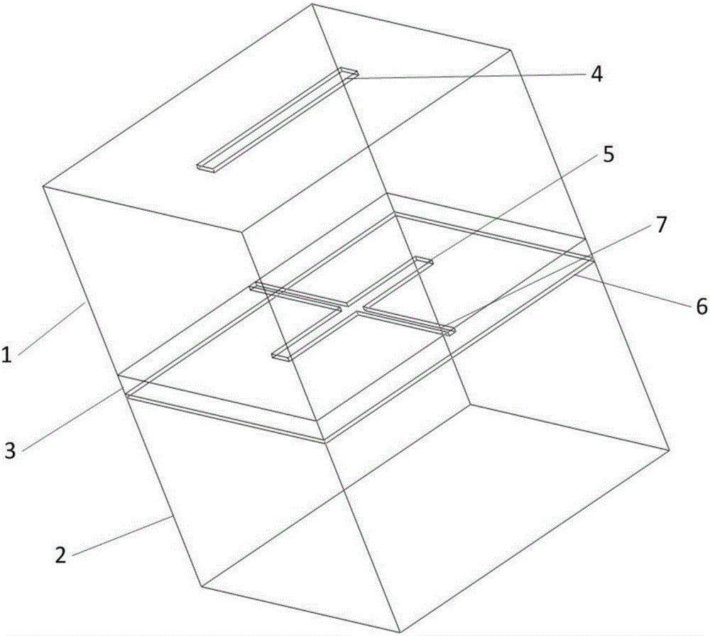
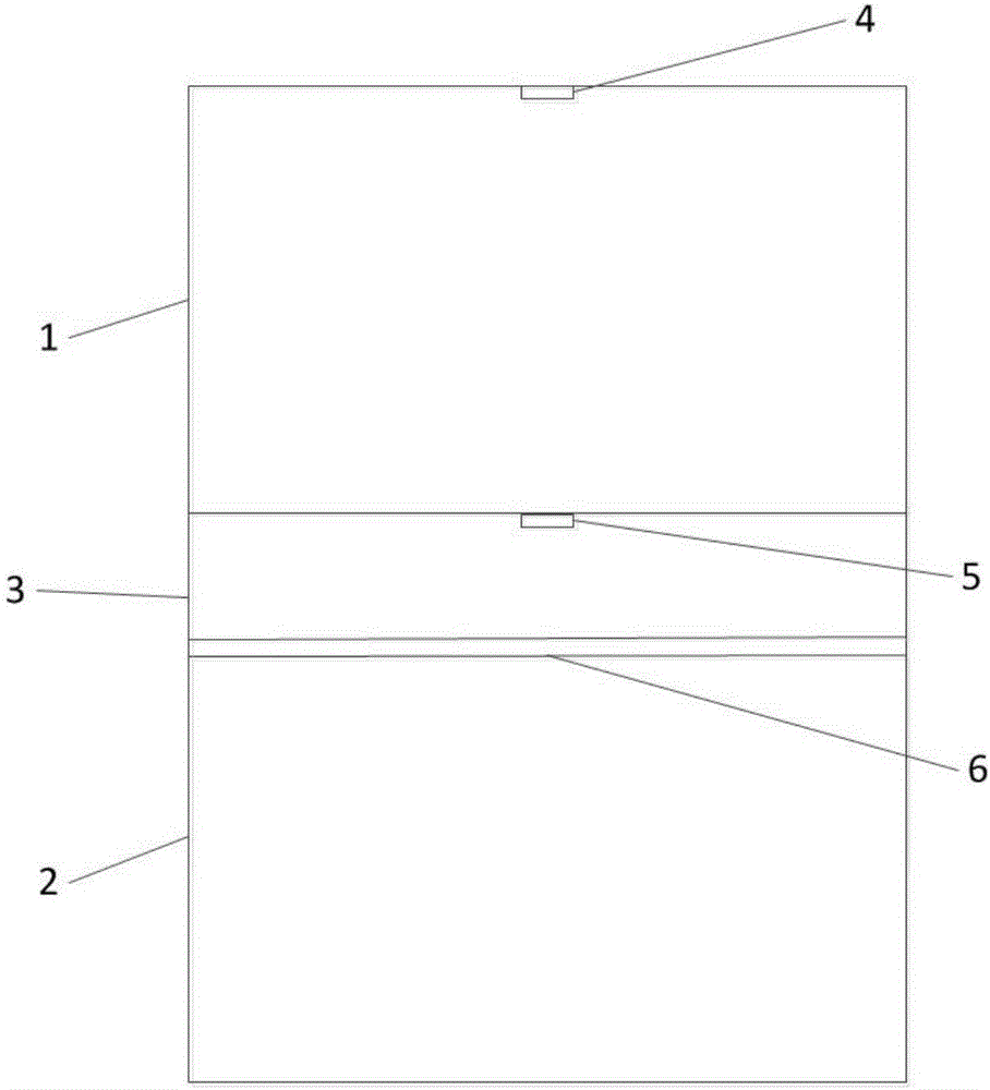
[0022] see figure 1 , image 3 , Figure 4 and Figure 5 , the structure of the liquid crystal phase shifting unit in this embodiment is: an interlayer is formed by an upper dielectric substrate 1 and a lower dielectric substrate 2 parallel to each other, and a nematic liquid crystal is sealed in the interlayer to form a liquid crystal layer 3, and in the upper layer A metal microstrip structure is formed on the surface of the dielectric substrate and the lower dielectric substrate, and a bias voltage is applied by using the metal microstrip structure, and a bias electric field is formed in the liquid crystal layer to change the alignment direction of the liquid crystal molecules in the liquid crystal layer , thereby changing the dielectric constant of the liquid crystal layer and changing the phase of the reflected wave.

[0023] In specific implementation, the corresponding structural settings also include:

[0024] The upper dielectric substrate and the lower dielectric...


PUM


Abstract

The invention discloses a liquid crystal phase shift unit and a phased antenna composed of the same. The liquid crystal phase shift unit is characterized in that a sandwich layer is formed by an upper-layer dielectric substrate and a lower-layer dielectric substrate which are arranged in parallel, nematic liquid crystal is enclosed in the sandwich layer to form a liquid crystal layer, metal micro-strip structures are formed on the surface of the upper-layer dielectric substrate and the surface of the lower-layer dielectric substrate, bias voltage is applied by means of the metal micro-strip structures, bias field is formed in the liquid crystal layer to enable the arrangement direction of liquid crystal molecules in the liquid crystal layer to be changed, and then the dielectric constant of the liquid crystal layer is changed and the phase position of reflected waves is changed; in an array formed by the liquid crystal phase shift unit, needed phase distribution is realized by applying different voltages to different units, so that corresponding wave beam directions are obtained or wavefront beamforming is achieved. Phase shift characteristics are changed with an electrical control method, working at the frequency band of 100-1000 GHz can be achieved, machining is easy, miniaturization is achieved, and cost is low.

Description

technical field [0001] The invention belongs to the imaging and radar fields of terahertz electronics, in particular to a liquid crystal reflective phase-shifting unit and a phase-controlled reflective array antenna composed of the same. Background technique [0002] Compared with traditional mechanical scanning antennas, phased array antennas have faster and more accurate beam scanning capabilities. Can achieve farther target search and more stable and reliable performance. [0003] The microstrip reflectarray antenna combines the advantages of the traditional parabolic reflector antenna and the microstrip array antenna. It has high radiation efficiency and wide beam scanning angle. The core of microstrip reflectarray research is how to design the structure and size of each unit, so that it can achieve specific phase compensation for the incident wave, thus forming a specific beam. The traditional microstrip reflectarray antenna mainly has the following design methods, o...

Claims


Application Information

Patent Timeline
IPC IPC(8): G02F1/13H01Q3/30
CPCG02F1/1313H01Q3/30
Inventor 杨军蔡成刚叶明旭尹治平邓光晟陆红波阮久福
Owner HEFEI UNIV OF TECH
Why Eureka
Try Eureka