Eureka AIR delivers breakthrough ideas for toughest innovation challenges, trusted by R&D personnel around the world.

Fault current limiters (fcl) with the cores staurated by superconducting coils

a superconducting coil and current limiter technology, applied in the direction of emergency protective circuit arrangement, emergency protection arrangement for limiting excess voltage/current, electrical equipment, etc., can solve the problem of limiting the increase of current, the impedance of the ac coil does not reach its maximum possible value, and the current limiter's impedance builds up, etc. problem, to achieve the effect of reducing the effective impedance of the fcl, reducing the weight and dimension of the devi

Inactive Publication Date: 2006-07-20
BAR ILAN UNIV
View PDF11 Cites 31 Cited by
  • Summary
  • Abstract
  • Description
  • Claims
  • Application Information

AI Technical Summary

Benefits of technology

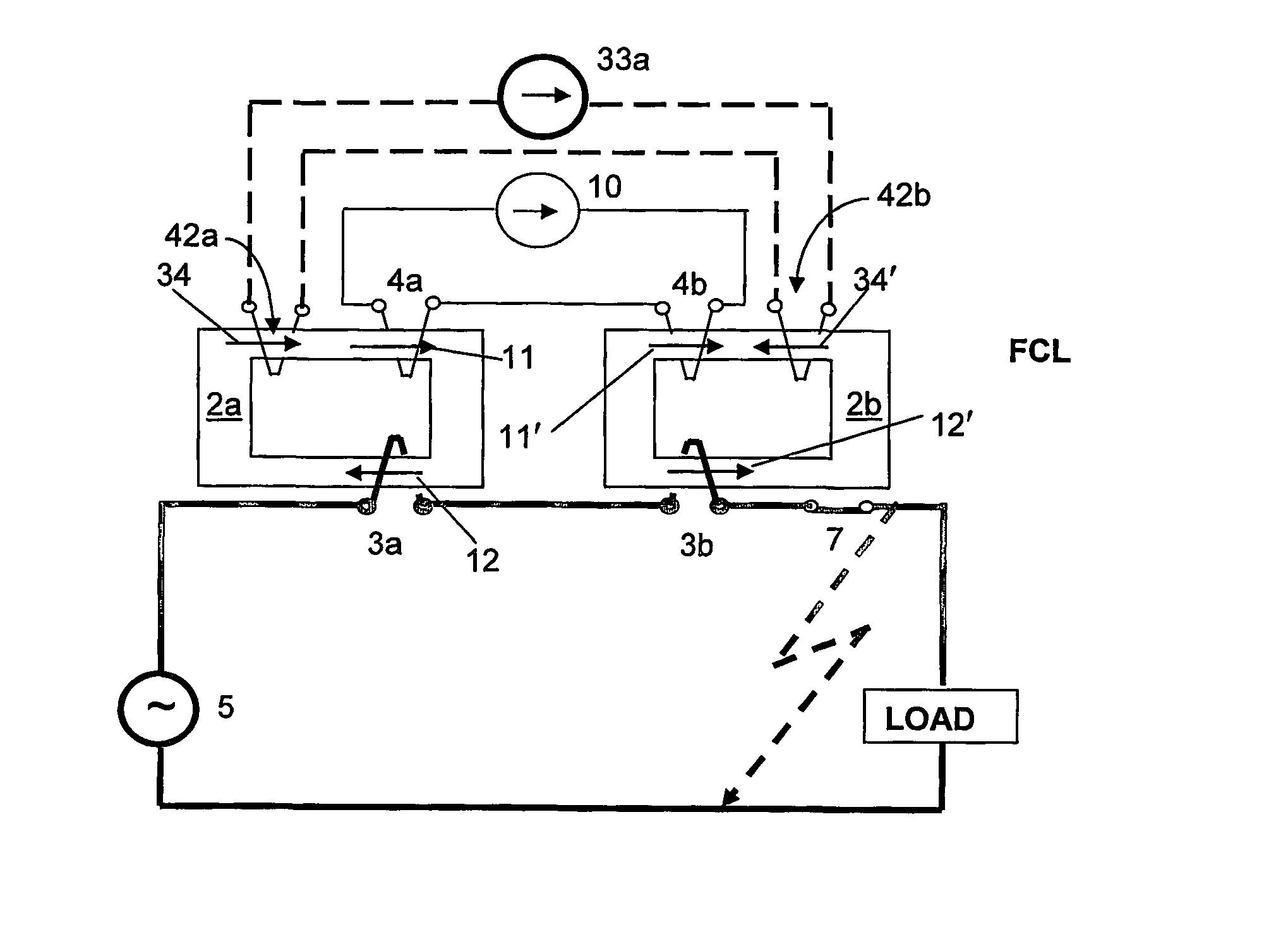
[0030] There may also be optionally provided feedback coils that are energized at the moment of increasing voltage on the FCL and fully or partially compensate for the magnetizing effect of the bias coils, thus increasing effective permeability of the cores such that the impedance of the AC coils increases. The feedback coils can be energized, for example, from an independent DC power supply controlled by voltage drop on FCL or by a power supply connected in parallel to the FCL and including a step-down transformer and rectifier. In the latter case, the input voltage of the power supply is proportional to the voltage drop across the FCL. At normal operation, current in the feedback coils is very small and has no influence on FCL operation. At fault conditions, the current in the feedback coils increases to compensate for the magnetizing effect of the bias coils. It is important that the current in the feedback coils reaches the necessary threshold during the first half cycle after a fault event to decrease the initial rise in current. The feedback coils can be made of copper wire with relatively small cross-section because they operate for only short time (4-5 half-cycles) and the resulting heating is therefore small.
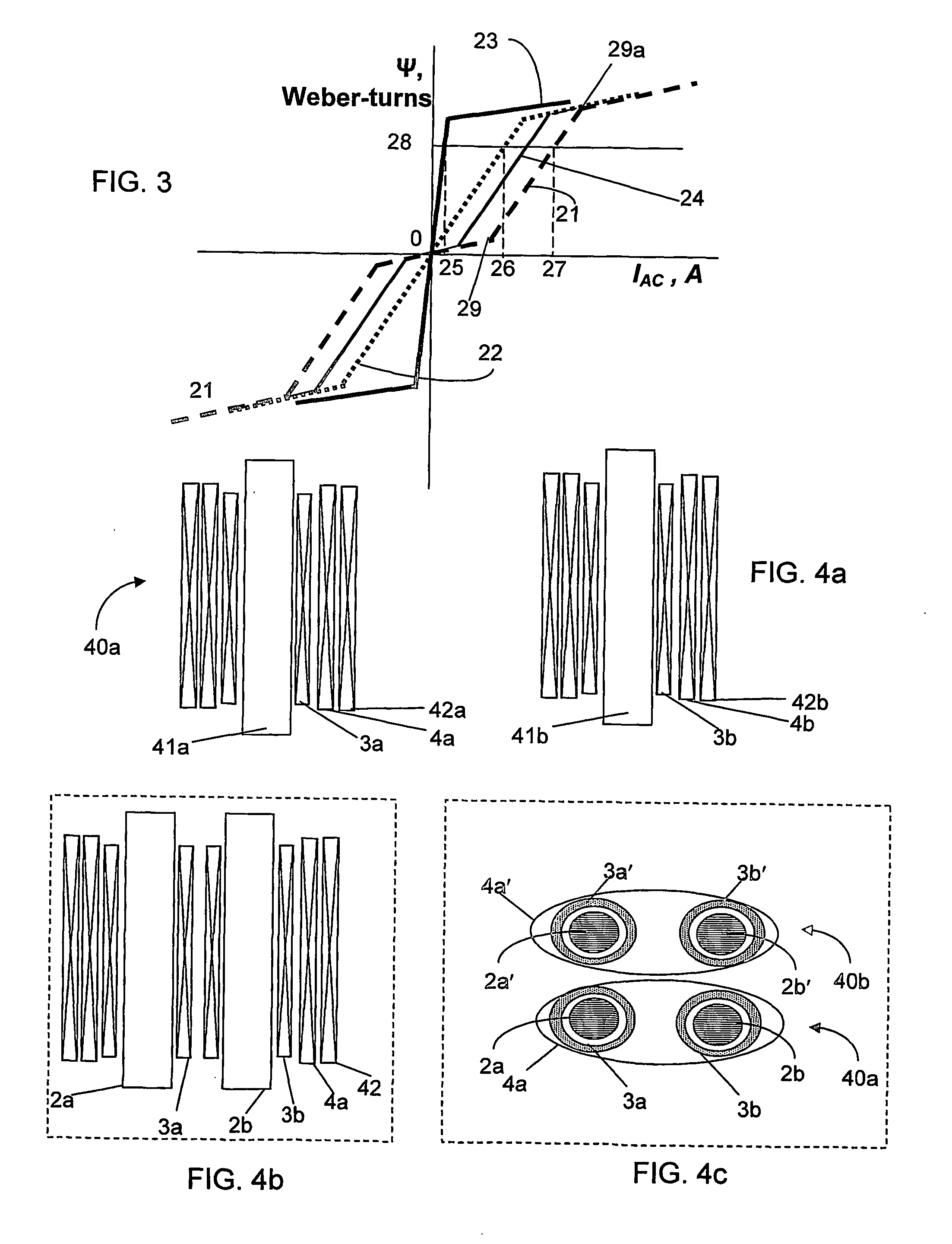
[0051] According to a further embodiment of the present invention, in order to decrease manufacturing cost of the current limiter, it is assembled with standard modules that have the optimal size for the convenience of manufacturing and installation.

Problems solved by technology

As a result the impedance of the current limiter builds up and limits the increase of the current.
Also, in known FCLs of this type the impedance of the AC coils does not reach its maximum possible value because the bias coils produce the magnetic flux in the cores that reduces the impedance of AC coils.
This feature is necessary at normal conditions but it has a negative effect at fault conditions.
Furthermore, at fault conditions the alternating magnetic field of the AC coils affects the superconducting bias coil, decreasing its critical current.

Method used


Image

  • Fault current limiters (fcl) with the cores staurated by superconducting coils
  • Fault current limiters (fcl) with the cores staurated by superconducting coils
  • Fault current limiters (fcl) with the cores staurated by superconducting coils

Examples


Embodiment Construction

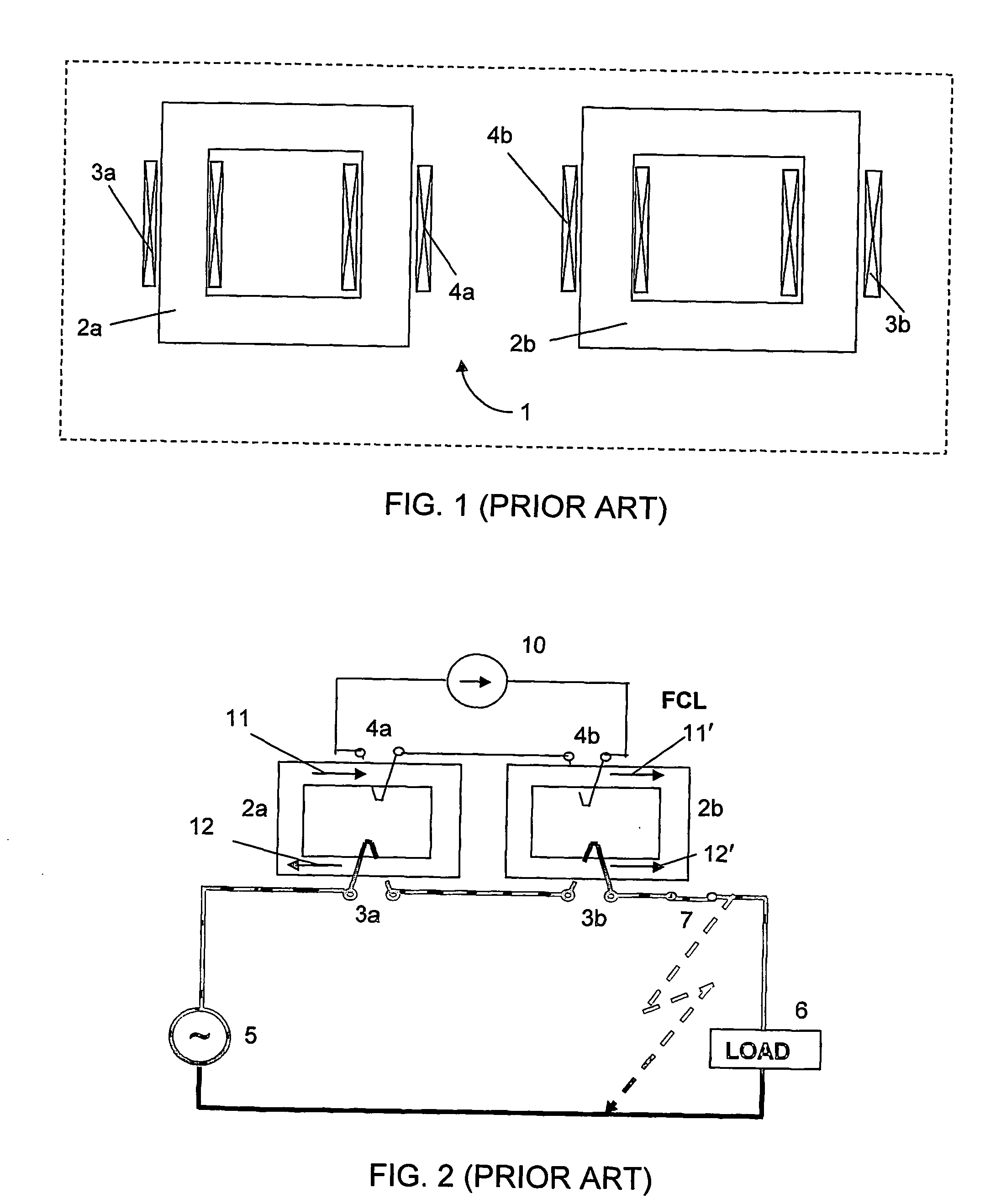
[0061] In the following description various embodiments are described. To the extent that many features are common to different embodiments, identical reference numerals will be employed to refer to components that are common to more than one figure.

[0062] In order more fully to appreciate the benefit of the invention, it will be instructive first to consider a typical prior art single phase FCL. To this end, FIG. 1 shows pictorially a prior art saturated core single phase FCL designated generally as 1 having a pair of closed magnetic cores 2a and 2b each supporting a respective AC coil 3a and 3b. The cores further support a pair of DC superconducting bias coils 4a and 4b.

[0063]FIG. 2 shows schematically a circuit diagram showing the single phase FCL 1 in use. An AC supply 5, typically from the electric power grid, is connected to a load 6 via a circuit breaker 7. In series with the load 6 are connected the two AC coils 3a and 3b of the FCL. The respective superconducting bias coi...


PUM


Abstract

A superconducting short circuit current limiter (40a) for an alternating current system includes AC reactors having superconducting direct current bias windings (4a, 4b) that at normal conditions maintain the reactor's cores in saturated state. There are at least two AC coils (3a, 3b) for each phase operating at opposite half periods or at both half periods. The reactor may also have an additional feedback coil (42a, 42b) that at least partly compensates for the bias field of the superconducting coil at fault conditions enhancing a limiting capacity of the reactor. The reactor's core can be configured for decreasing its dimensions and mass as compared with known devices and for decreasing core losses. High voltage / high current devices include several standard modules connected in series or / and in parallel. A positional relationship of the modules is defined for decreasing necessary numbers of Amp?re-turns of superconducting and non-superconducting coils.

Description

FIELD OF THE INVENTION [0001] This invention relates to current limiting devices for AC electric grid. REFERENCES [0002] In the following description, reference will be made to the following non-patent publications: [0003] [1] B. P. Raju, K. C. Parton, T. C. Bartram, “A current limiting device using superconducting d.c. bias: applications and prospects,”IEEE Transactions on Power Apparatus &Systems, vol. 101, pp.3173-3177, 1982. [0004] [2] J. X. Jin, S. X. Dou., C. Grantham, and D. Sutanto “Operating principle of a high T-c superconducting saturable magnetic core fault current limiter”. Physica C, 282, Part 4: p. 2643-2644, 1997. [0005] [3] J. X. Jin, S. X. Dou., C. Cook, C. Grantham, M. Apperley, and T. Beals, “Magnetic saturable reactor type HTS fault current limiter for electrical application”. Physica C, 2000.341-348: p.2629-2630. [0006] [4] V. Keilin, I. Kovalev, S. Kruglov, V. Stepanov, I. Shugaev, V. Shcherbakov, I.Akimov, D. Rakov, and A. Shikov, “Model of HTS three-phase sa...

Claims


Application Information

Patent Timeline
IPC IPC(8): H02H9/00H02H9/02
CPCH02H9/021H02H9/023Y02E40/69Y02E40/60
Inventor FRIEDMAN, ALEXANDERZARUDI, MOSHESHAKED, NOAMWOLFUS, SHUKISINVANI, MOSHEYESHURUN, YOSEF
Owner BAR ILAN UNIV
Why Eureka
Eureka Blog
Learn More