Self-shielded CT scanner

a ct scanner and self-shield technology, applied in applications, instruments, nuclear engineering, etc., can solve the problems of expensive and still crowded leaded material lining of the room

Active Publication Date: 2009-09-22
XORAN TECH
View PDF28 Cites 3 Cited by
  • Summary
  • Abstract
  • Description
  • Claims
  • Application Information

AI Technical Summary

Benefits of technology

[0009]In operation, the part of the body to be scanned is positioned between the x-ray source and detector. A table for supporting the part of the body to be scanned is small enough to fit between the x-ray source and detector. The lead shields rotate with the gantry and prevent the x-ray from reaching the operator while the CT scanner is in operation. By limiting the area reached by the x-ray the exposure of the operator is limited to an acceptable amount allowing the operator to safely be in the same room as CT scanner when using the computer.
[0010]Accordingly, the lead shields of this invention provide sufficient shielding to protect the operator and the room is not required to be lined with lead.

Problems solved by technology

Unfortunately, the operator of the system must still be protected from the x-rays emitting from the CT scanner.
Therefore, rooms must still be lined with leaded material, which is expensive.

Method used


Image

  • Self-shielded CT scanner
  • Self-shielded CT scanner
  • Self-shielded CT scanner

Examples


Embodiment Construction

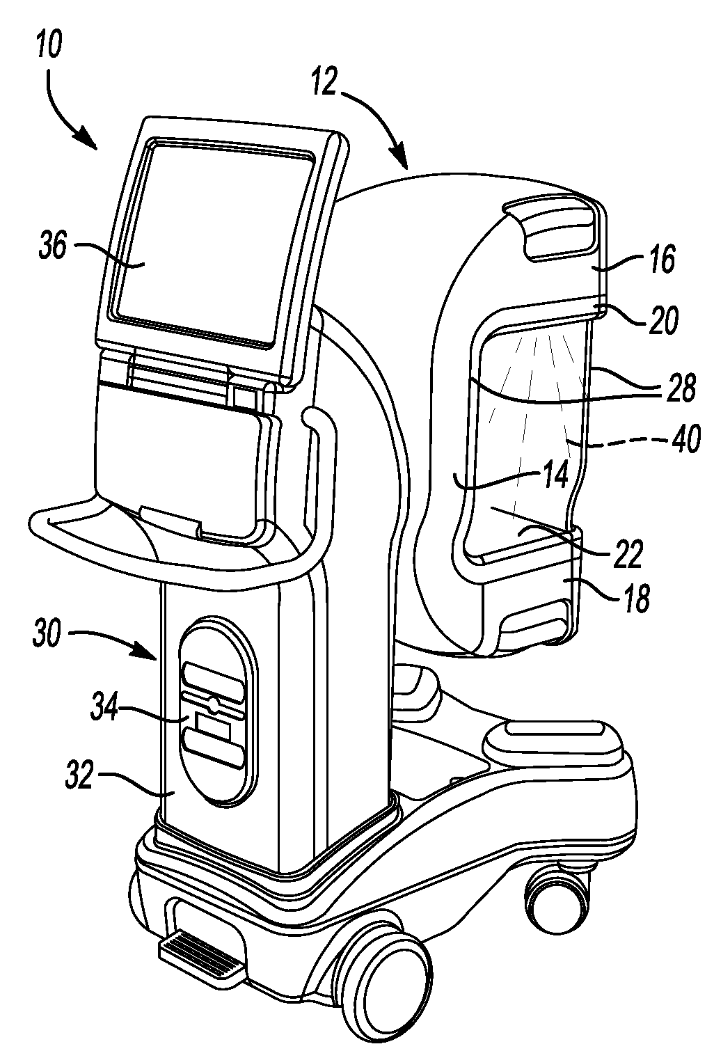
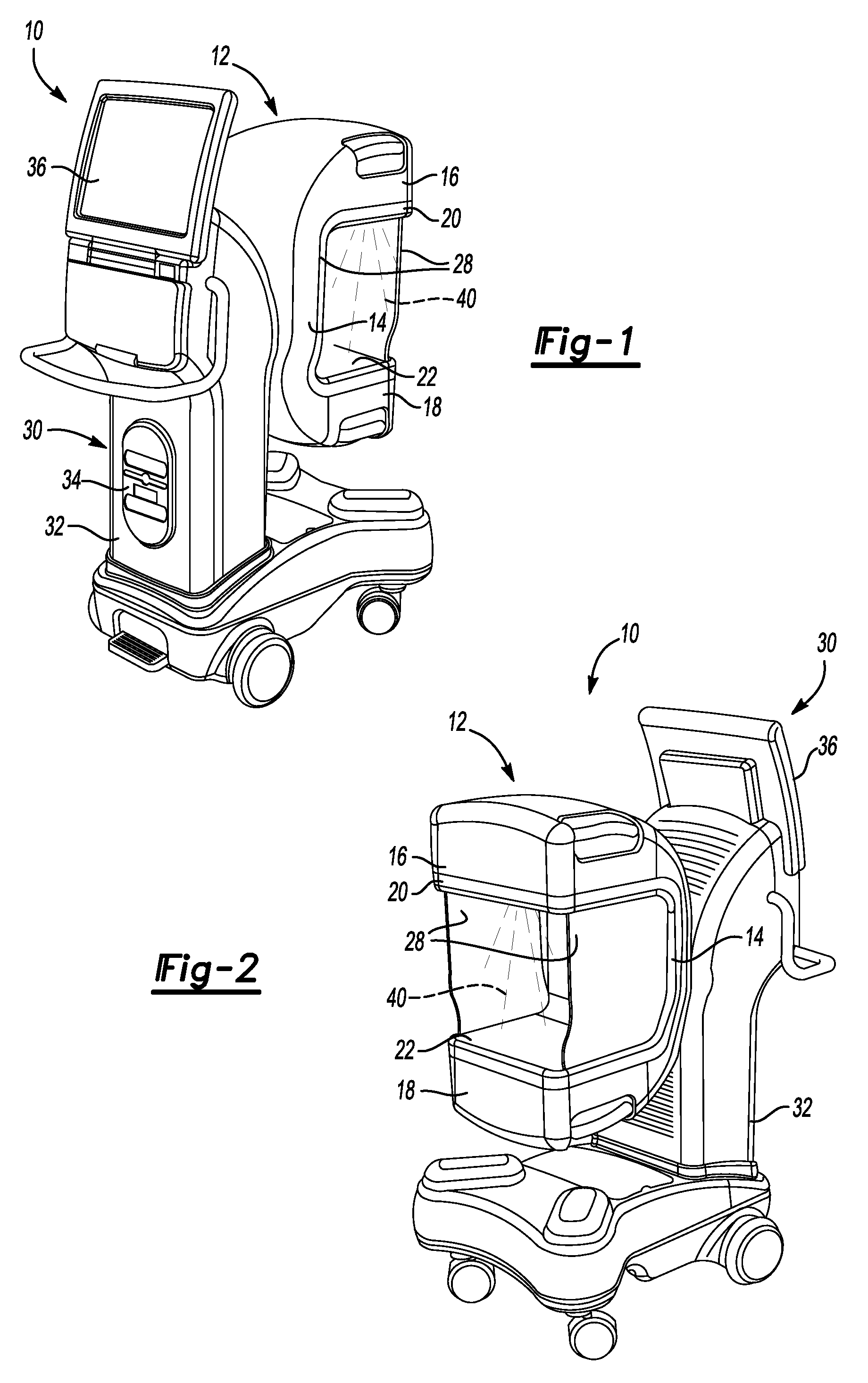
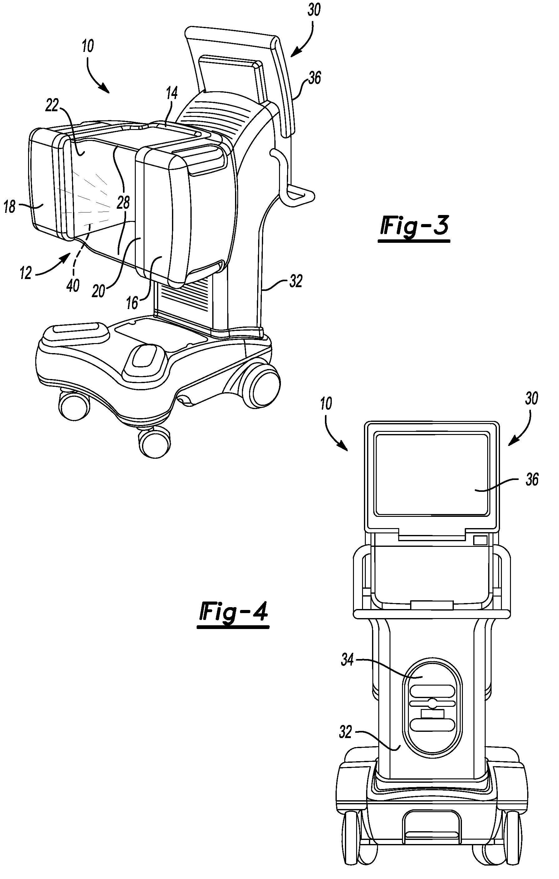
[0020]FIGS. 1 thru 8 illustrate a CT scanner 10 according to the present invention wherein all of the components are contained in a gantry 12. The gantry 12 provides the structural support and housing for the components. The gantry 12 comprises a cross-bar section 14 from which a first arm 16 and a second arm 18 extend perpendicularly from either end, forming a c-shaped assembly.

[0021]The first arm 16 houses the x-ray source 20, which in this embodiment is a cone-beam x-ray source 20. The second arm 18 houses a complementary detector 22. The cross-bar section 14 of the gantry 12 houses a motor for rotating the gantry 12 relative to a mounting plate 26. Lead shields 28 are located on opposing sides of the x-ray source 20. The shields 28 extend between the x-ray source 20 and the detector 22. The shields 28 are preferably leaded glass to prevent the patient from feeling closed in during use. The shields 28 may also be leaded plexiglass or some other polymer or other material that does...


PUM


Abstract

A CT scanner includes a pair of shields to protect an operator from x-rays from the CT scanner. The CT scanner has a gantry that provides structural support and housing for the components including an x-ray source and a detector arranged on the gantry to face one another. Lead shields are located on opposing sides of the x-ray source and extend between the x-ray source and the detector. The CT scanner further includes a computer located on an opposing side of the gantry from the x-ray source and the detector. The lead shields rotate with the gantry and prevent the x-ray from reaching the operator while the CT scanner is in operation.

Description

[0001]This application claims priority to U.S. Provisional Application Ser. No. 60 / 773,232, filed Feb. 14, 2006.STATEMENT REGARDING FEDERALLY SPONSORED RESEARCH OR DEVELOPMENT[0002]This invention made with government support under grant number R44CA107895, awarded by the National Institute of Health (NIH). The government has certain rights in the invention.BACKGROUND OF THE INVENTION[0003]The present invention relates generally to computer tomography (CT) scanners and more particularly to a compact CT scanner which provides shielding of the operator from the x-rays.[0004]Generally, CT scanners are large enough to scan a patient's entire body. An x-ray source is mounted on a movable ring, which also includes an array of x-ray detectors opposite the x-ray source. The patient lies on a platform that moves through the ring. The ring is rotated so the x-ray source and detectors revolve around the patient taking a series of x-rays, while the patient is moved through the ring on the platfo...

Claims


Application Information

Patent Timeline
Patent Type & Authority Patents(United States)
IPC IPC(8): H05G1/60H01J35/16
CPCA61B6/4405A61B6/107
Inventor SUKOVIC, PREDRAGCLINTHOME, NEALRAKIC, MIODRAGBERTOLINA, JAMES A.STAYMAN, JOSEPH WEBSTER
Owner XORAN TECH
Why Eureka
Try Eureka