Leaned high pressure compressor inlet guide vane

a high-pressure compressor and guide tube technology, applied in the direction of machines/engines, stators, liquid fuel engines, etc., can solve the problems of reducing the effective inlet area of the stage, stalling or surge of the blade, and stress that manifests itself at the root or inner radial ends, so as to reduce the stress placed

Inactive Publication Date: 2009-09-29
RTX CORP
View PDF7 Cites 12 Cited by
  • Summary
  • Abstract
  • Description
  • Claims
  • Application Information

AI Technical Summary

Benefits of technology

[0010]The inventors have discovered that it would be desirable to have variable geometry guide vane assemblies that reduce stress placed on downstream compressor blades in gas turbine engines.
[0011]The invention circumferentially leans the guide vanes away from the pressure side at the outer radial diameter, effectively pushing the engine core air flow radially, towards the outer diameter and reducing airflow separations on the guide vane near the outer radial diameter. This allows for aerodynamic stresses on the downstream rotor blades to be reduced.

Problems solved by technology

As with airplane wings, in some conditions the blades can stall or surge.
The aerodynamic vanes turn the airstreams through an angle to meet the blades of a following compressor stage and reduce the effective inlet area of the stage.
A problem experienced with current variable geometry guide vane designs is a stress that manifests itself at the root, or inner radial ends of the downstream compressor blades.
The unsteady air pushes and pulls on the blades, stressing where they couple to an inner concentric engine structure.
Radial inlet guide vanes do not direct a uniform velocity of air across the downstream compressor blades as their geometry changes in response to engine demands.
As a result, the compressor blades experience an unbalanced loading of air velocities with slower moving, separated air concentrated near the outer radial end regions.

Method used


Image

  • Leaned high pressure compressor inlet guide vane
  • Leaned high pressure compressor inlet guide vane
  • Leaned high pressure compressor inlet guide vane

Examples


Embodiment Construction

[0023]Embodiments of the invention will be described with reference to the accompanying drawing figures wherein like numbers represent like elements throughout. Further, it is to be understood that the phraseology and terminology used herein is for the purpose of description and should not be regarded as limiting. The use of “including,”“comprising,” or “having” and variations thereof herein is meant to encompass the items listed thereafter and equivalents thereof as well as additional items. The terms “mounted,”“connected,” and “coupled” are used broadly and encompass both direct and indirect mounting, connecting, and coupling. Further, “connected” and “coupled” are not restricted to physical or mechanical connections or couplings.

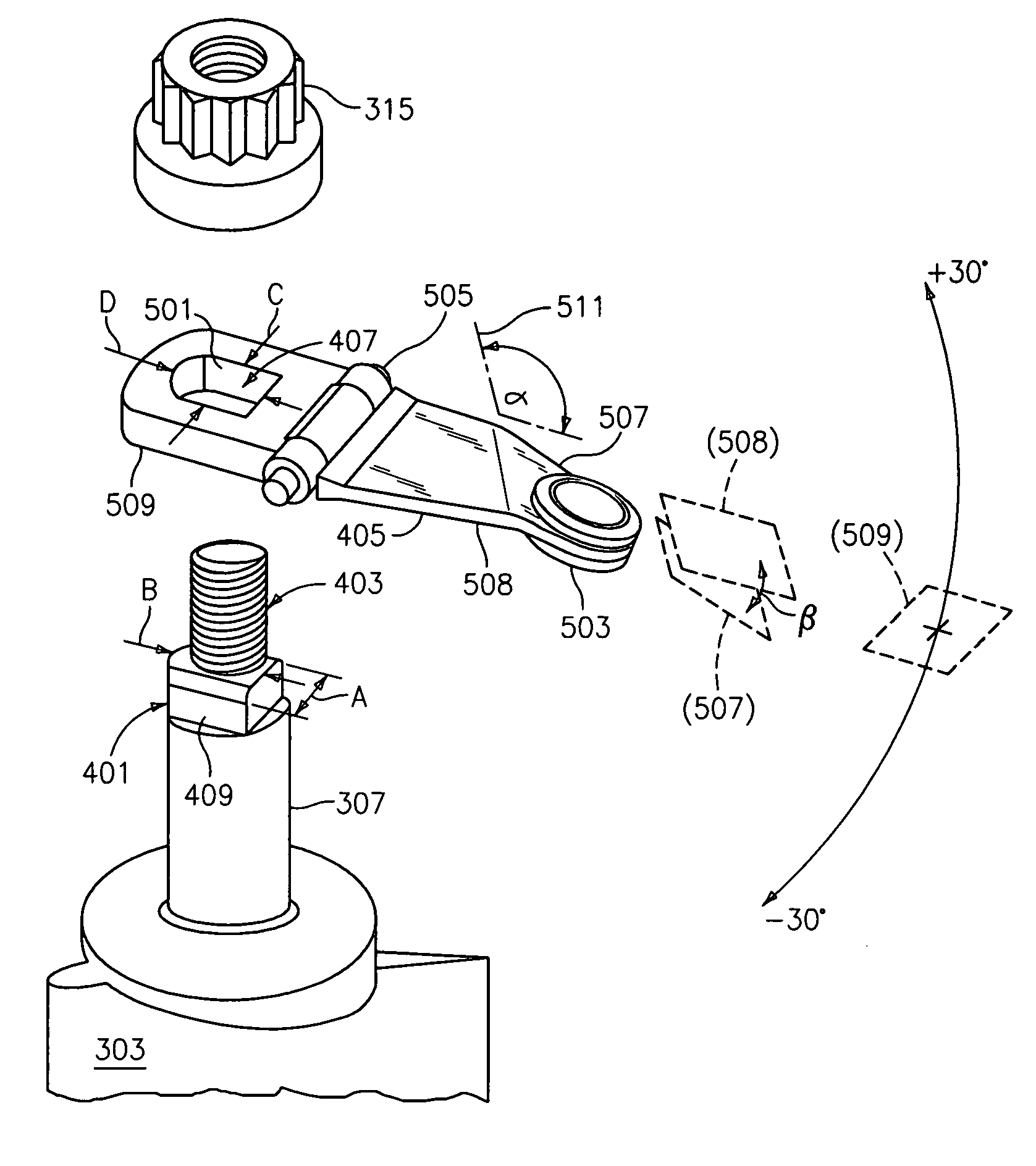
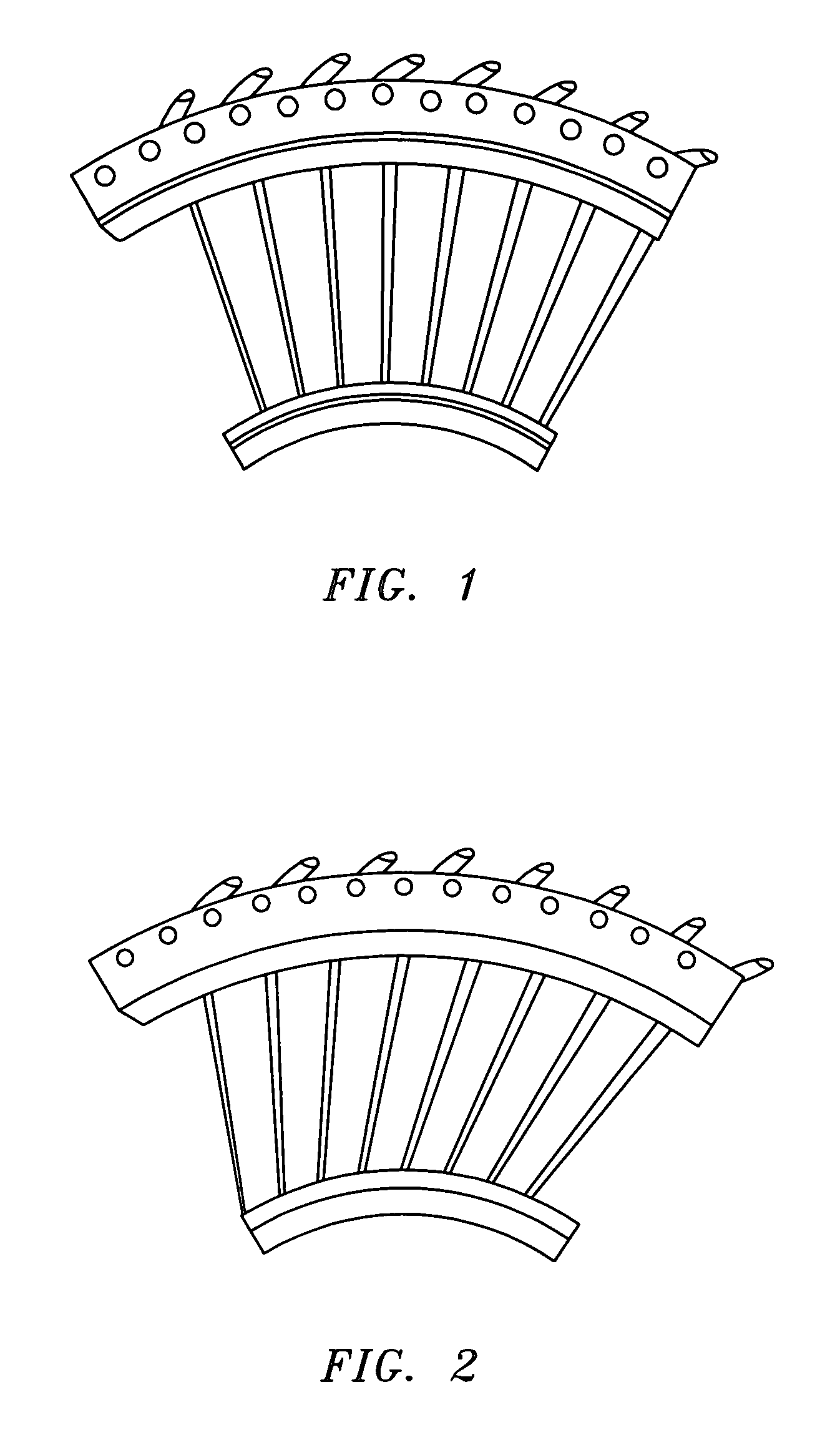
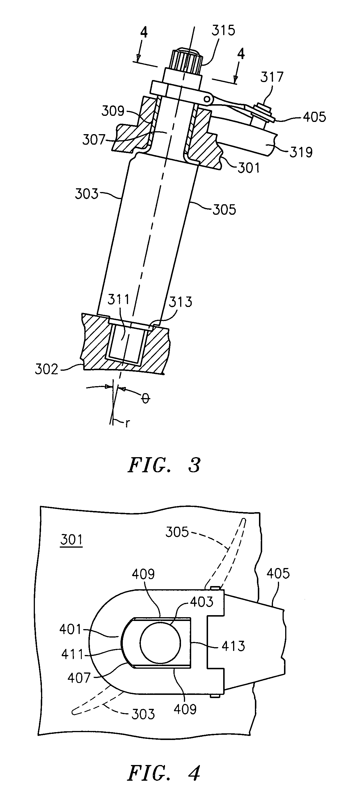
[0024]The invention is a variable geometry leaned inlet guide vane assembly as shown in FIGS. 2, 3 and 6. The invention “leans” each guide vane away from the pressure side (direction of rotation) at the outer radial end. The lean for each vane may be set ...


PUM


Abstract

A variable geometry inlet guide vane assembly that reduces stress placed on downstream compressor blades in gas turbine engines. The invention circumferential leans upstream guide vanes, pushing engine core air flow radially. This allows for aerodynamic stresses on the downstream blades to be reduced. The invention overcomes the difference in movement between a unison ring and a vane arm by providing a hinge in conjunction with a spherical bearing that couples to the unison ring.

Description

BACKGROUND OF THE INVENTION[0001]The invention relates generally to the field of variable geometry guide vanes for gas turbine engines. More specifically, the invention relates to variable geometry guide vane assemblies that reduce stress placed on downstream compressor blades.[0002]A gas turbine engine compressor typically includes inlet guide vanes followed by a row, or stage of compressor rotor blades. A fan (military style) or high pressure compressor will only have one row of inlet guide vanes. There may be other rows of variable vanes, but they may differ in their principle of operation. During operation, air is sequentially compressed by the compressor stages. The compressed air is channeled to a combustor and mixed with fuel and ignited. The hot combustion gases generated power the engine.[0003]Axial compressors rely on spinning blades that have airfoil sections similar to airplane wings. As with airplane wings, in some conditions the blades can stall or surge. If this occur...

Claims


Application Information

Patent Timeline
Patent Type & Authority Patents(United States)
IPC IPC(8): F01D9/00
CPCF01D17/162F04D29/563F05D2250/314F05D2260/50F05D2260/79
Inventor MERRY, BRIAN D.SHARMA, OM PARKASHSUCIU, GABRIEL L.ALFORD, WILLIAM E.
Owner RTX CORP
Why Eureka
Try Eureka