Air-circulating, ionizing, air cleaner

a technology of air cleaner and air circulating, which is applied in the direction of external electric electrostatic separator, vapor flow control, electrode construction, etc., can solve the problems of uncharged surfaces, ionized particles that are not collected on the collecting plate have a tendency to collect on adjacent uncharged surfaces, and dust and oil aerosols will still be present, so as to prevent hand injury, facilitate cleaning, and suppress the lateral escape of ions

Inactive Publication Date: 2009-09-29
HEADWATERS RES & DEV
View PDF6 Cites 10 Cited by
  • Summary
  • Abstract
  • Description
  • Claims
  • Application Information

AI Technical Summary

Benefits of technology

[0012]According to one variant of the invention, this guide cylinder and charged collecting plate are located vertically above the ion-emitting needle source. By placing the charged collecting plate above the ion source, an upwardly directed ion wind is formed. Air entrained by the ion wind approaches the ion source laterally and is then swept upwardly by the flux of ions introduced into the airflow by the ionizing needle. The collecting plate, located above the needle, does not block this upward flow of air but rather serves to guide the air flow.
[0022]Another optional feature of the invention is the provision of a protective circuit which is incorporated within the power supply of the unit. Because the ionizing needles and collection cylinder are open to the outside world, a person can place his or her hand inside the device, close to the ionizing needles. In this case, a charge will be imparted on the body of the person and if the person then touches the collector electrode, he or she may get an unpleasant spark between their hand and such collector. To eliminate this effect, a sensing circuit is incorporated in the power supply that turns off the unit as soon as the slightest discharge occurs on the collector. Conveniently, the reset switch for this safety circuit can also serve as an on-off switch.

Problems solved by technology

Although the collecting plate will attract and hold a substantial part of the dust present in the air flow, nevertheless some dust and oily aerosols will still be present in the air flow that moves past the collecting plate.
It has been found that such ionized particles as are not collected on the collecting plate have a tendency to collect on adjacent uncharged surfaces, such as walls.
This is an undesirable effect.
This disadvantage arises because this air cleaner acts as a “fountain of ions” with its collection surface positioned beneath the ion source, requiring ions to flow outwardly before being collected.
The design of U.S. Pat. No. 6,176,977 does not, however, address confining the ion-wind induced airflow, or providing an airflow path that will minimize interference with such airflow.

Method used


Image

  • Air-circulating, ionizing, air cleaner
  • Air-circulating, ionizing, air cleaner
  • Air-circulating, ionizing, air cleaner

Examples


Embodiment Construction

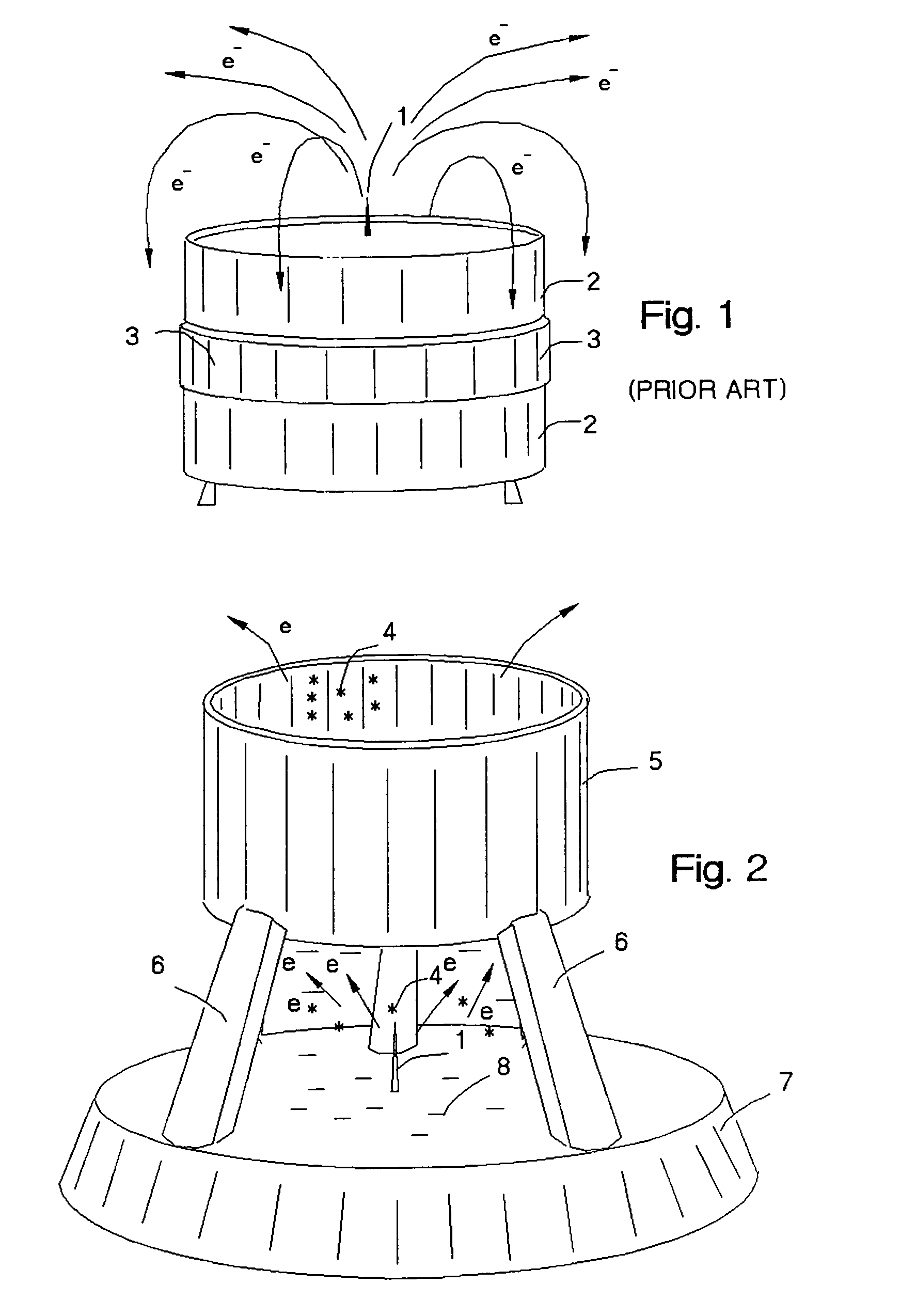
[0033]FIG. 1 shows the prior art air cleaner unit mentioned in the U.S. Pat. No. 5,538,692 wherein the ionizing needle 1 is located on top of the insulated body of the unit 2. Collecting element 3 is located below the ionizing needle 1. Charged particles 4 flow away from the needle 1 and some are collected by the collector 3 and some are released in all directions into the surrounding space.

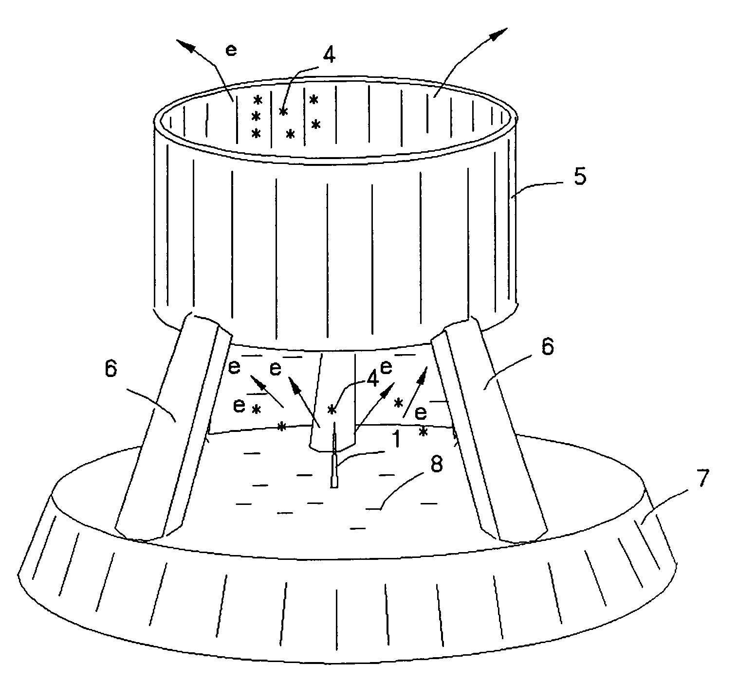
[0034]FIG. 2 shows the variant of the present invention where a conducting cylinder 5 is located above the ionizing needle 1. The collector cylinder 5 is supported by insulating supports 6 over insulating base 7. Ions “e” generated by the needle 1 are attracted towards the inside surface of the cylinder 5, which also collects dust which has been charged by the ions. At the same time, the adjacent surrounding surface 8 around the base of the needle 1 becomes charged by the ions “e” created by needle 1 and acts as a repellant to the ions “e” with the result that the ions “e” are focused in the upwa...


PUM


Abstract

An air cleaner is described wherein an ion wind is generated by an ionizing element and directed to pass over a dust collector surface. By proper design and adjustment of the ionizing element and collector, the unit can be operated without emitting charged particles, if any, in other than the direction of orientation of the dust collector surface and thus avoiding smudging of the surrounding walls. The collector may be cylindrical in form and may be separately detachable, rendering it readily available for cleaning.

Description

[0001]This application is a continuation application of application Ser. No. 10 / 355,198, now abandoned, filed by the same inventor on Jan. 31, 2003 which, in turn, is a continuation-in-part of application Ser. No. 10 / 067,433 filed Feb. 7, 2002, now U.S. Pat. No. 6,919,053.FIELD OF THE INVENTION[0002]This invention relates to air filtration systems. In particular it relates to an air filtration system based upon forming an air current of ionized air and the collection from such air current of dust particles by means of a charged surface.BACKGROUND OF THE INVENTION[0003]U.S. Pat. No. 5,538,692 to Joannou describes an ionizing type air cleaner having an exposed ionizing needle and a collector element in the form of a charged, partially conducting, surface. (See FIG. 1) Ions released from the needle spread-out through the air of the surrounding environment in the form of an “ion wind”, charging particles of dust present therein. By reason of the charge on the collecting surface, such du...

Claims


Application Information

Patent Timeline
Patent Type & Authority Patents(United States)
IPC IPC(8): B01J19/08B03C3/40B03C3/12B03C3/36B03C3/41B03C3/47B03C3/49B03C3/68
CPCB03C3/12B03C3/36B03C3/68B03C3/49B03C2201/14
Inventor JOANNOU, CONSTANTINOS
Owner HEADWATERS RES & DEV
Why Eureka
Try Eureka