Vehicle propulsion system

a technology for propulsion systems and vehicles, applied in the direction of vehicle sub-unit features, vehicle propulsion using engine-driven generators, multi-dynamo-motor starters, etc., can solve the problems of less effective vehicle operation, performance or fuel efficiency reduction, etc., and achieve the effect of reducing performance or fuel efficiency of the vehicl

Active Publication Date: 2009-09-29
GENERAL ELECTRIC CO
View PDF50 Cites 81 Cited by
  • Summary
  • Abstract
  • Description
  • Claims
  • Application Information

AI Technical Summary

Problems solved by technology

While the above described systems are effective during various driving conditions, they may be less effective when the vehicle is operated at relative low speeds as seen during typical urban driving.
As a result, the performance or fuel efficiency of the vehicle may be reduced.

Method used


Image

  • Vehicle propulsion system
  • Vehicle propulsion system
  • Vehicle propulsion system

Examples


Embodiment Construction

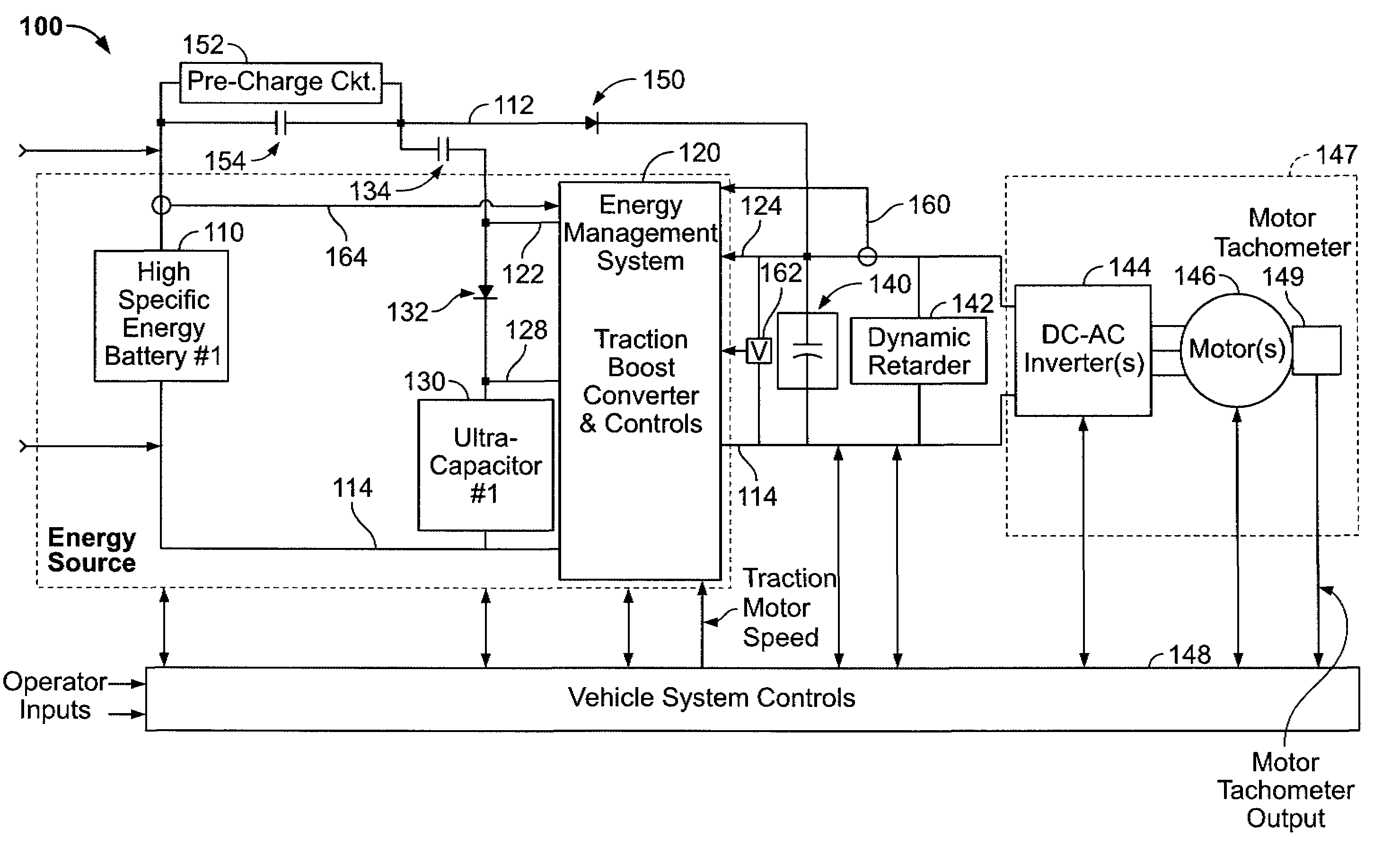
[0022]Described herein are control and power storage systems that may be utilized with an electric or hybrid vehicle. Hybrid vehicle as used herein represents a vehicle that utilizes a combination of an electric motor and a heat engine to provide propulsive force to the vehicle. Moreover, as used herein, an electric vehicle represents a vehicle that includes a motor and a plurality of batteries, wherein the batteries provide at least a portion of the propulsive force to operate the vehicle.

[0023]The systems include an alternating current (AC) traction drive, a first energy storage system electrically connected to the traction drive through a direct current (DC) link, a second energy storage system electrically connected to the traction drive such that the voltage output from the energy storage system is decoupled from the DC link using a bi-directional boost converter, and a uni-directional current device that is poled to conduct current from low voltage side of the boost converter ...


PUM


Abstract

A vehicle propulsion includes an alternating current (AC) traction drive, a first energy storage system electrically coupled to the traction drive through a direct current (DC) link, a second energy storage system electrically coupled to the traction drive such that the voltage output from the second energy storage system is decoupled from the DC link using a bi-directional boost converter, and an energy management system configured to control said first and second energy storage systems when the vehicle is operating in at least one of a pre-charge mode and a normal operation mode with the traction drive system enabled.

Description

CROSS REFERENCE TO RELATED APPLICATIONS[0001]This application is entitled to the benefit of, and claims priority to, provisional U.S. Patent Application Ser. No. 60 / 759,991 filed Jan. 18, 2006, and entitled “Electric Drive Energy Management System Control with Multiple Energy Storage Units”, which is hereby incorporated by reference in its entirety.BACKGROUND OF THE INVENTION[0002]This invention relates generally to vehicle drive systems and, more particularly, to battery powered drive systems such as are used in battery powered electric vehicles or hybrid vehicles.[0003]FIG. 1 illustrates a known alternating current (AC) electric drive system that is used in battery electric vehicles and also hybrid vehicles. As shown, the energy storage unit, which may be a battery, is electrically connected to the direct current (DC) link of an DC-AC traction inverter.[0004]FIG. 2 illustrates a known hybrid drive system that includes a first battery that is coupled to the low voltage side of the ...

Claims


Application Information

Patent Timeline
Patent Type & Authority Patents(United States)
IPC IPC(8): B60K6/28B60L11/12B60W20/00B60K6/48B60L50/15
CPCB60K6/28B60L7/06B60L7/14B60L7/24B60L11/005B60L11/123B60L11/1803B60L11/1861B60Y2400/114B60L2210/14B60W30/18127Y02T10/6217Y02T10/6221Y02T10/6278Y02T10/7005Y02T10/7022Y02T10/7044Y02T10/705Y02T10/7077Y02T10/7225B60K6/48B60L50/40B60L50/61B60L50/51B60L58/12Y02T10/62Y02T10/70Y02T10/72Y02T10/92Y02E60/10B60Y2400/3086B60Y2400/3084Y02T10/7072
Inventor KING, ROBERT DEANHUANG, XIANGHUIKILINSKI, GARY RAYMOND
Owner GENERAL ELECTRIC CO
Why Eureka
Try Eureka