Double-ended isolated DC-DC converter

a converter and isolated technology, applied in the direction of electric variable regulation, process and machine control, instruments, etc., can solve the problems of disadvantageous complex circuit configuration and difficulty in reducing the size and weight of the converter, and achieve the effect of high-efficiency power conversion

Active Publication Date: 2009-09-29
MURATA MFG CO LTD
View PDF11 Cites 17 Cited by
  • Summary
  • Abstract
  • Description
  • Claims
  • Application Information

AI Technical Summary

Benefits of technology

[0009]To overcome the problems described above, preferred embodiments of the present invention provide a compact and lightweight double-ended isolated DC-DC converter that maintains a highly efficient power conversion by driving switches on a primary side and a synchronous rectifier on a secondary side with substantially complementary timing.

Problems solved by technology

Accordingly, the circuit configuration is disadvantageously complicated.
Thus, it is difficult to reduce the size and weight of the converter.

Method used


Image

  • Double-ended isolated DC-DC converter
  • Double-ended isolated DC-DC converter
  • Double-ended isolated DC-DC converter

Examples


first preferred embodiment

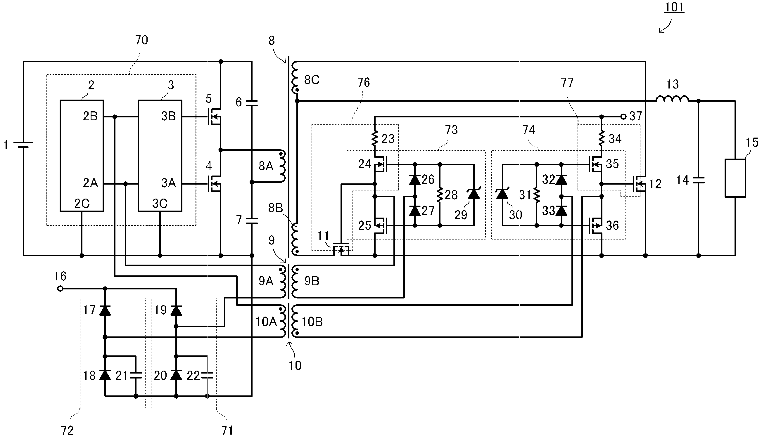
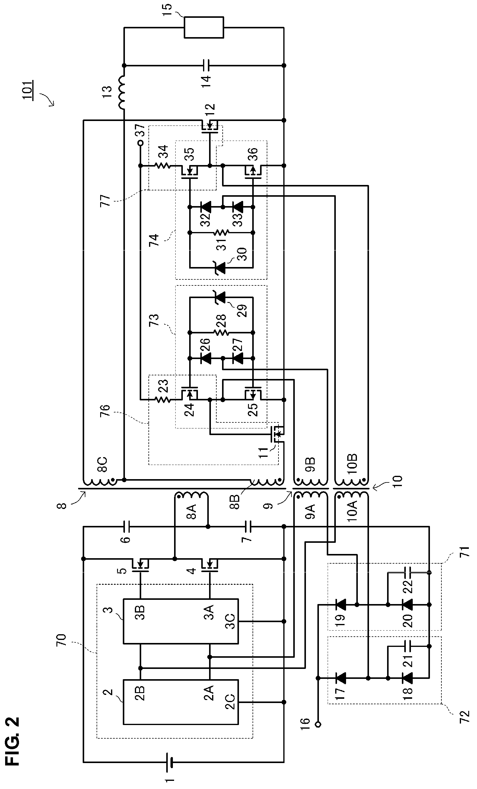
[0032]FIG. 2 is a circuit diagram of a double-ended isolated DC-DC converter according to a first preferred embodiment of the present invention. FIG. 3 is a waveform diagram of the main portion of the double-ended isolated DC-DC converter. FIGS. 4A to 4D are diagrams illustrating the structure of a transformer used in the first preferred embodiment.

[0033]As shown in FIG. 2, a double-ended isolated DC-DC converter 101 includes a main transformer 8 having a primary coil 8A and a secondary coil 8B, a first power switch 4 and a second power switch 5 connected to the primary side of the main transformer 8, a primary side control circuit 70 arranged to control switching operations of the first power switch 4 and the second power switch 5. The double-ended isolated DC-DC converter 101 further includes a first synchronous rectifier 11, a second synchronous rectifier 12, and a choke coil 13 connected to a secondary side of the main transformer 8.

[0034]The double-ended isolated DC-DC converte...

second preferred embodiment

[0080]FIG. 5 is a circuit diagram of a double-ended isolated DC-DC converter according to a second preferred embodiment of the present invention. The double-ended isolated DC-DC converter has a basic structure similar to that of the first preferred embodiment.

[0081]However, as shown in FIG. 5, a double-ended isolated DC-DC converter 102 includes a first synchronous rectifier side delay circuit 76 and a second synchronous rectifier side delay circuit 77 having a structure different from that illustrated in FIG. 2. In the preferred embodiment shown in FIG. 2, a gate charging current of the first synchronous rectifier 11 and the second synchronous rectifier 12 is restricted by the resistors 23 and 34 so that the turn-on timing points of the first synchronous rectifier 11 and the second synchronous rectifier 12 are delayed by third and fourth delay times K and L, respectively. Thus, the occurrence of a short-circuit current is prevented. However, due to variation in the input capacitanc...

third preferred embodiment

[0088]FIG. 6 is a circuit diagram of a double-ended isolated DC-DC converter according to a third preferred embodiment of the present invention.

[0089]In order to reduce a manufacturing cost, a double-ended isolated DC-DC converter 103 does not include the high side driver 3 shown in FIG. 2. Accordingly, the second power switch 5 having a reference potential (source) that is disconnected from the ground is driven using the second pulse transformer 10.

[0090]As shown in FIG. 6, in order to obtain driving power of the second power switch 5, a bootstrap circuit 54 including a capacitor 56 and a diode 55 is provided. A series circuit of an FET 58, an FET 59, and a resistor 57 is connected between an output unit of the bootstrap circuit 54 and the ground on a primary side. A connection point between the FET 58 and the FET 59 is connected to the gate of the second power switch 5. A circuit of diodes 60 and 61, a zener diode 63, and a resistor 62 is connected to the gates of the FET 58 and t...


PUM


Abstract

In a double-ended isolated DC-DC converter, by using a main transformer and first and second pulse transformers, a first power switch of a primary side circuit and a first synchronous rectifier of a secondary side circuit are driven with complementary timing, and a second power switch of the primary side circuit and a second synchronous rectifier of the secondary side circuit are driven with complementary timing. A first turn-off edge signal and a first turn-on edge signal generated in a primary side control circuit are transmitted to the secondary side via the first pulse transformer so as to generate a driving signal of the first synchronous rectifier. In addition, a second turn-off edge signal and a second turn-on edge signal generated in a primary side circuit are transmitted to the secondary side via the second pulse transformer so as to generate a driving signal of the second synchronous rectifier.

Description

BACKGROUND OF THE INVENTION[0001]1. Field of the Invention[0002]The present invention relates to a double-ended isolated DC-DC converter, such as a half bridge DC-DC converter, a push-pull DC-DC converter, or a full bridge DC-DC converter.[0003]2. Description of the Related Art[0004]FIG. 1 illustrates an example of an existing double-ended isolated DC-DC converter. A double-ended isolated DC-DC converter 120 includes an external drive circuit 114, totem-pole drivers 116 and 118, a DC level shifter 121, a first switch driver 122, a second switch driver 124, primary side switches Q1 and Q2, a main transformer T1, a signal transmission transformer T2, a first synchronous rectifier Q3, a second synchronous rectifier Q4, a first switch Q5, a second switch Q6, a third switch Q7, a fourth switch Q8, a choke coil Lo, an output smoothing capacitor Co, resistors R1, R2, R3, and R4, capacitors C1, C2, C3, and C4, and diodes D1, D2, D3, and D4.[0005]In the double-ended isolated DC-DC converter ...

Claims


Application Information

Patent Timeline
Patent Type & Authority Patents(United States)
IPC IPC(8): H02M7/68
CPCH02M3/33592H02M2001/0064Y02B70/1475Y02B70/10H02M1/0064
Inventor MATSUMOTO, TADAHIKO
Owner MURATA MFG CO LTD
Why Eureka
Try Eureka