Timing recovery in error recovery for iterative detection

a technology of error recovery and iterative detection, applied in the field of decoding systems, can solve the problems of particularly unreliable associated bit values produced by iterative detectors, and achieve the effects of reducing raw bit error rate, improving signal accuracy, and fast decoding

Inactive Publication Date: 2009-09-29
SEAGATE TECH LLC
View PDF4 Cites 34 Cited by
  • Summary
  • Abstract
  • Description
  • Claims
  • Application Information

AI Technical Summary

Benefits of technology

[0011]The invention is a decoding system that includes an improved timing loop for use in error recovery mode operations, in which “fast decode” bit values that are used for timing recovery purposes in the normal modes of operation are replaced, at an appropriate iteration in the error recovery mode, with detected bit values from an iterative detector. The replacement occurs after a reread operation in which the timing loop maintains lock. The iteratively decoded bit values, which are associated with the decoding of the entire data block, are associated with a lower raw bit error rate than the fast decode bit values. Accordingly, the timing loop is able to more closely track the bit rate of the read signal and the decoder then operates with more accurate signal values.
[0012]More specifically, the decoder includes a loss of lock detector, which in the embodiment described below determines the running average of the soft output of an iterative detector that operates over the entire data block. The system detects a loss of lock if the running average falls below a predetermined threshold. The loss of lock indicates that the associated bit values produced by the iterative detector are particularly unreliable. Accordingly, the bit values are not used for timing recovery in a next reread and decode operation. If, however, there is more confidence in the results produced by the iterative detector, i.e., there is no loss of lock, the system uses the bit values produced by the iterative detector for timing recovery in the next reread and decode operation.
[0013]The loss of lock detector may, but need not, operate in conjunction with ADC sample averaging, such that the system omits from the averaging the samples for which a loss of lock is detected. Accordingly, the averaging operates only on those rereads that presumably will aid in reducing non-repeatable noise in the read signal.

Problems solved by technology

The loss of lock indicates that the associated bit values produced by the iterative detector are particularly unreliable.

Method used


Image

  • Timing recovery in error recovery for iterative detection
  • Timing recovery in error recovery for iterative detection
  • Timing recovery in error recovery for iterative detection

Examples


Embodiment Construction

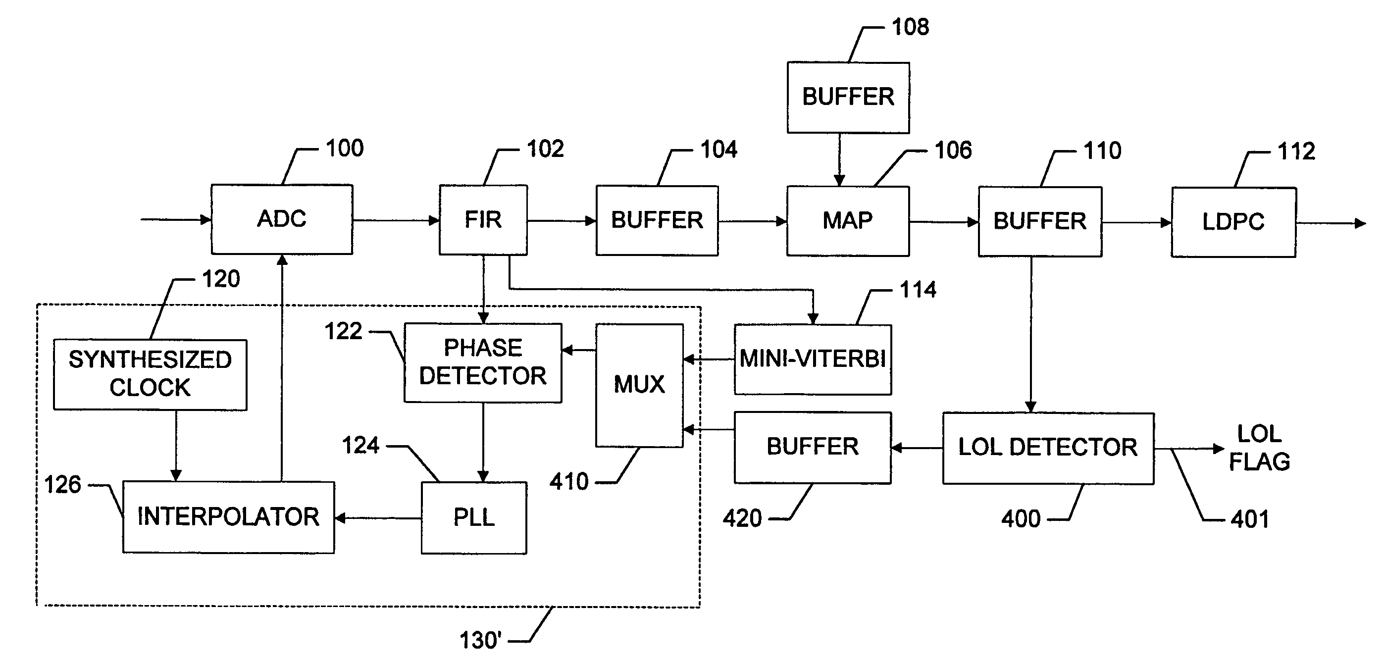
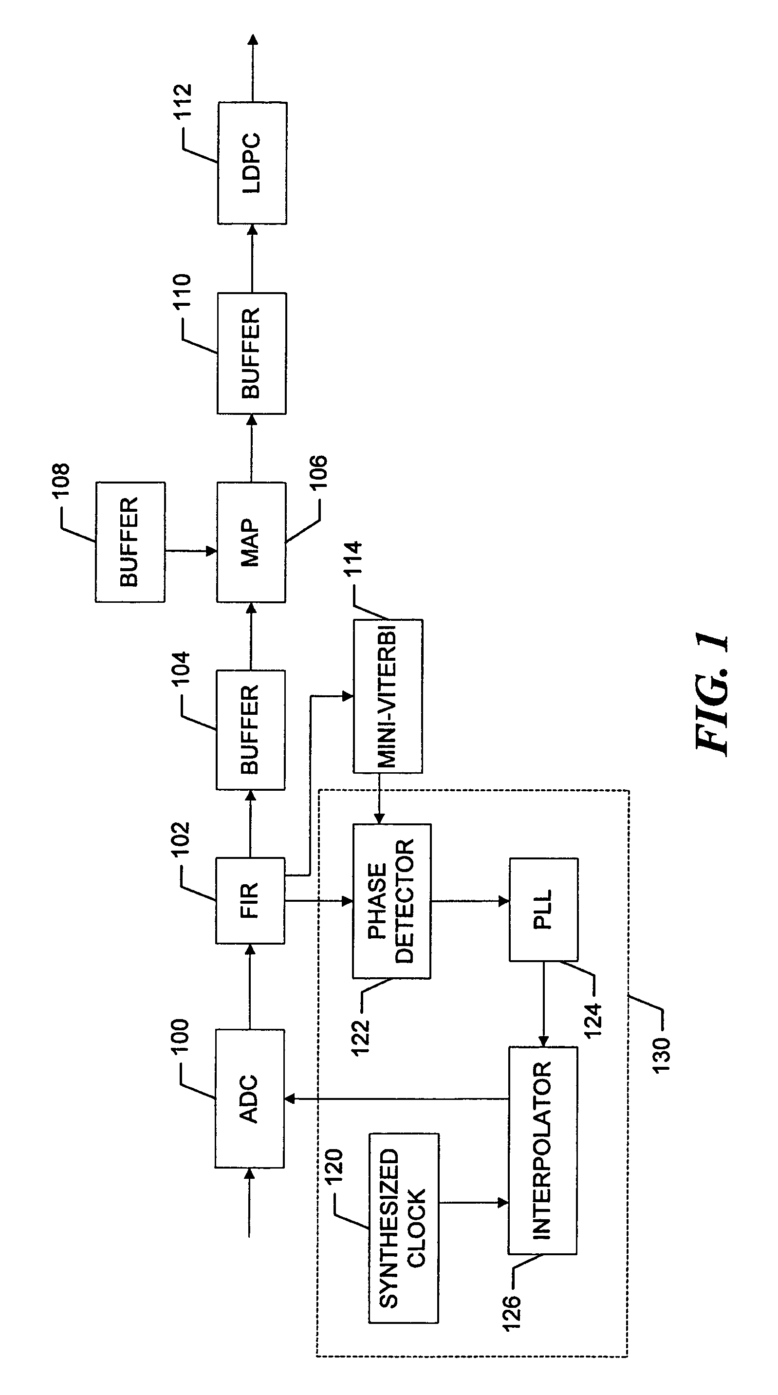
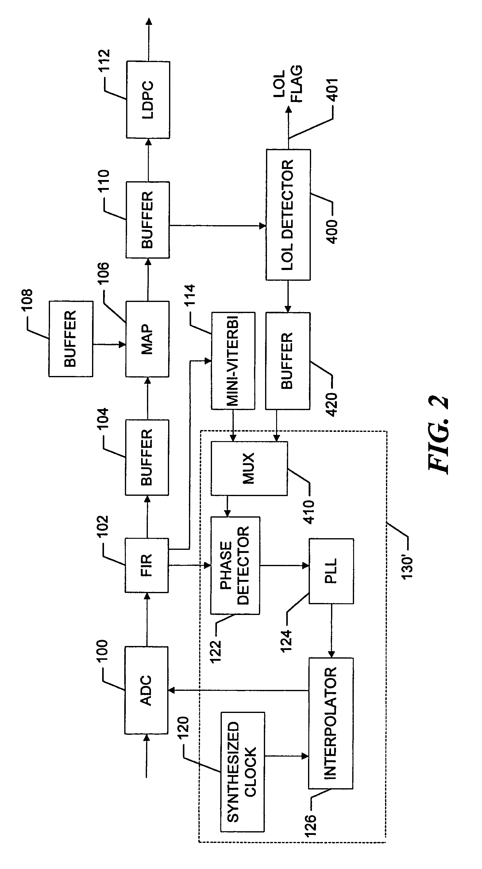
[0019]Referring now to FIG. 1, an analog read signal associated with reading a sector of a hard drive (not shown) is supplied to an analog-to-digital converter (ADC) 100. The ADC, which may be a flash ADC, operates in a known manner to sample the analog data signal and convert the samples to digital values. The ADC takes samples of the analog signal at times directed by a clock signal that is produced by a timing sub-system 130. The timing sub-system is described in more detail below.

[0020]The digitized samples produced by the ADC 10 are supplied to a finite impulse response filter (FIR) 102, which essentially shapes the samples for more reliable bit detection. The filtered data signal is supplied through a buffer 104 to a maximum a posteriori (MAP) detector 106. The MAP detector operates in a known manner to assign estimated bit values to the samples. The MAP detector produces input symbols, which consist of a bit value, or sign, and associated confidence information, and supplies ...


PUM


Abstract

A decoding system includes a timing loop for use in error recovery mode operations, in which “fast decode” bit values that are used for timing recovery purposes in the normal modes of operation are replaced, at an appropriate iteration in the error recovery mode, with detected bit values from an iterative detector. The replacement occurs after a reread operation in which the timing loop maintains lock.

Description

CROSS-REFERENCE TO RELATED APPLICATIONS[0001]The present application claims the benefit of U.S. Provisional Patent Application Ser. No. 60 / 720,991, which was filed on Sep. 27, 2005, by Jingfeng Liu et al. for a TIMING RECOVERY IN ERROR RECOVERY FOR ITERATIVE DETECTION and is hereby incorporated by reference.BACKGROUND OF THE INVENTION[0002]1. Field of the Invention[0003]The invention relates generally to decoding systems and, more particularly, to timing loops used in the decoder to control signal sampling.[0004]2. Background Information[0005]Increases in the storage capacities of hard disks or other storage devices result in read signals with smaller signal-to-noise ratios (SNRs). For better detection and decoding results with the lower SNRs, iterative detection and decoding methods, such as majority a posteriori (MAP) detecting and low-density parity check (LDPC) decoding are used to reproduce recorded data. The iterative methods work well at low raw bit error rates, and thus, the...

Claims


Application Information

Patent Timeline
Patent Type & Authority Patents(United States)
IPC IPC(8): H04L7/00H04L27/06
CPCG11B20/10009G11B20/10037G11B20/10046G11B20/10222G11B20/10296G11B20/14H04L7/0054G11B20/10425H04L7/0062G11B2020/185H04L7/0025
Inventor LIU, JINGFENGSHAO, ROSECHEN, JINGHUAN
Owner SEAGATE TECH LLC
Why Eureka
Try Eureka