Machine for machining optical workpieces, in particular plastic spectacle lenses

a technology for optical workpieces and machine tools, applied in the field of plastic spectacle lenses, can solve the problem of fine height displacement of the cutting edge of the turning tool, and achieve the effects of reducing the mass of weight, high-precision height adjustment of the turning tool, and reducing the weight of the mass

Active Publication Date: 2009-10-06
SATISLOH GMBH
View PDF34 Cites 16 Cited by
  • Summary
  • Abstract
  • Description
  • Claims
  • Application Information

AI Technical Summary

Benefits of technology

[0010]By virtue of the oblique position of the movement plane of the fast tool according to the invention in such a way that an angle of predetermined size exists between this movement plane and the plane containing the workpiece rotation axis, hence the workpiece rotation axis of the workpiece spindle, in conjunction with the adjustment movement of the workpiece spindle, which exists on the machine in any case, in the plane containing the workpiece rotation axis, more specifically in the direction of the workpiece spindle, a highly precise height adjustment of the turning tool cutting edge onto the workpiece rotation axis of the workpiece spindle can be achieved, without there being any need for height displacements of the turning tool cutting edge with respect to the fast tool arrangement. The extent of the adjustment movement of the workpiece spindle in the direction of its axis and thus the height compensation achieved thereby between the workpiece rotation axis of the workpiece spindle and the working point of the turning tool cutting edge depends on the sine function of the predetermined angle.
[0011]As a result, there is no need for any mechanical adjustment systems as are provided in the prior art and which, unlike the present invention, do not permit automatic height adjustment of the turning tool cutting edge during the machining operation. As a result, compared to the prior art, there is also a reduction in the weight of the masses that have to be moved by the fast tool arrangement, namely a reduction by the weight of the mechanical adjustment elements provided in the prior art between the turning tool and the shuttle of the fast tool arrangement, so that the dynamics and bandwidth of the fast tool arrangement are not limited by excessively high moving masses. This permits higher shape accuracy of the surfaces turned by the fast tool arrangement, and not least also leads to shorter machining times.
[0012]By virtue of the invention, not only is one complete adjustment axis saved and the number of required movement axes limited to a minimum, but also it is possible for the adjustment movements of tool (fast tool arrangement) and workpiece (workpiece spindle) to be split advantageously. For example, the adjustment movement of the workpiece spindle can be used to produce the rotationally symmetrical parts of a lens, that is to say the spherical part of the surface, while the non-rotationally symmetrical parts of the lens, as are present for example in the case of toric surfaces, prismatic surfaces, atoric surfaces or free-form surfaces, are produced via the adjustment movement of the fast tool arrangement. As a result, it is also possible to use fast tool arrangements with a shorter stroke and thus greater rigidity (due to the shorter lever), which in turn is beneficial to the quality of the surfaces produced.

Problems solved by technology

By manually adjusting a fine threaded screw, the entire flexural joint on the opposite side of the turning tool is deformed, resulting in very fine height displacement of the cutting edge of the turning tool.

Method used


Image

  • Machine for machining optical workpieces, in particular plastic spectacle lenses
  • Machine for machining optical workpieces, in particular plastic spectacle lenses
  • Machine for machining optical workpieces, in particular plastic spectacle lenses

Examples


Embodiment Construction

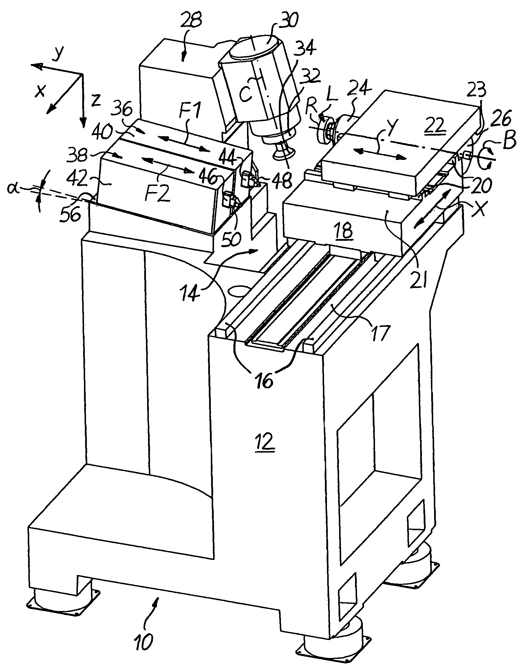
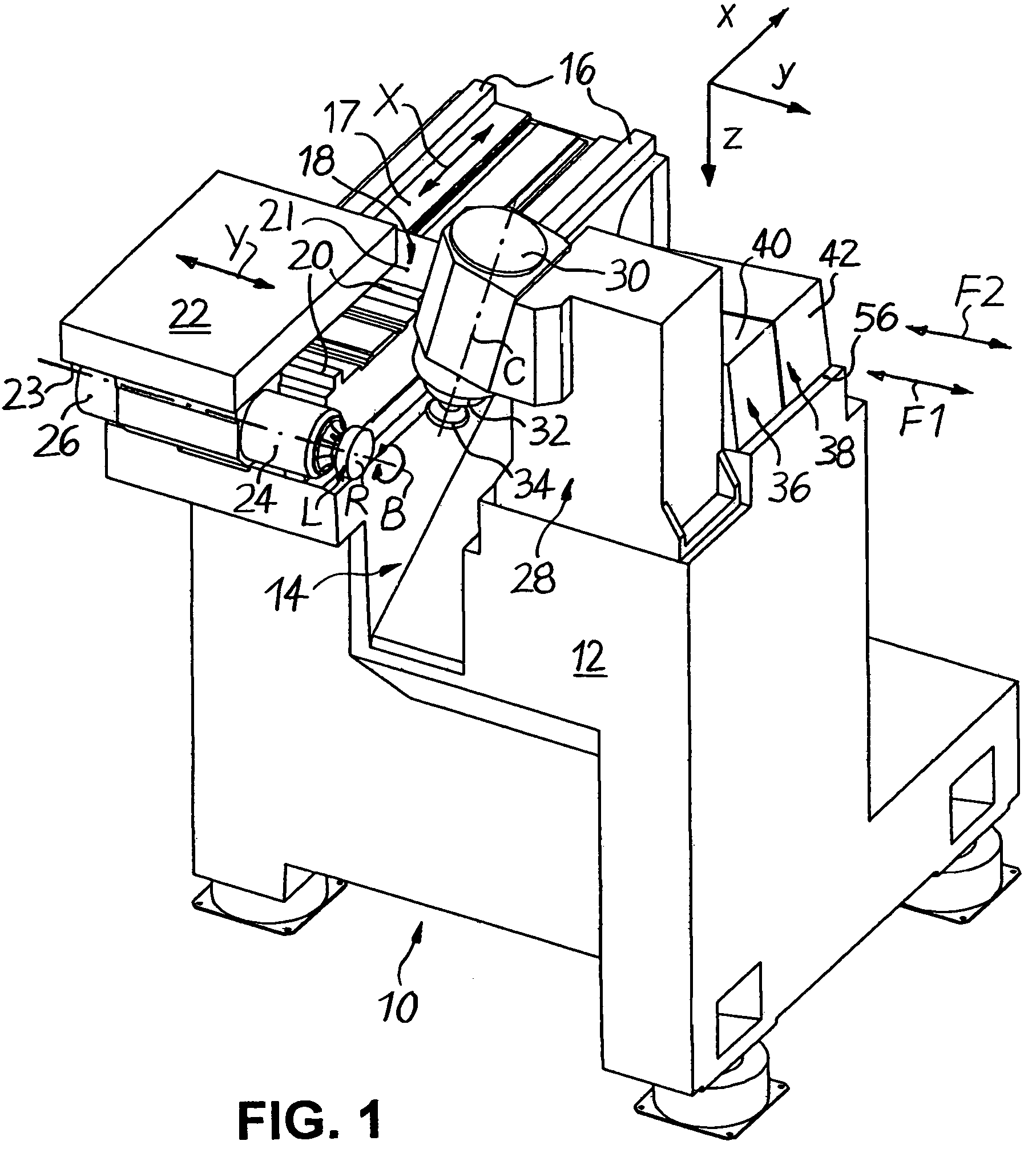
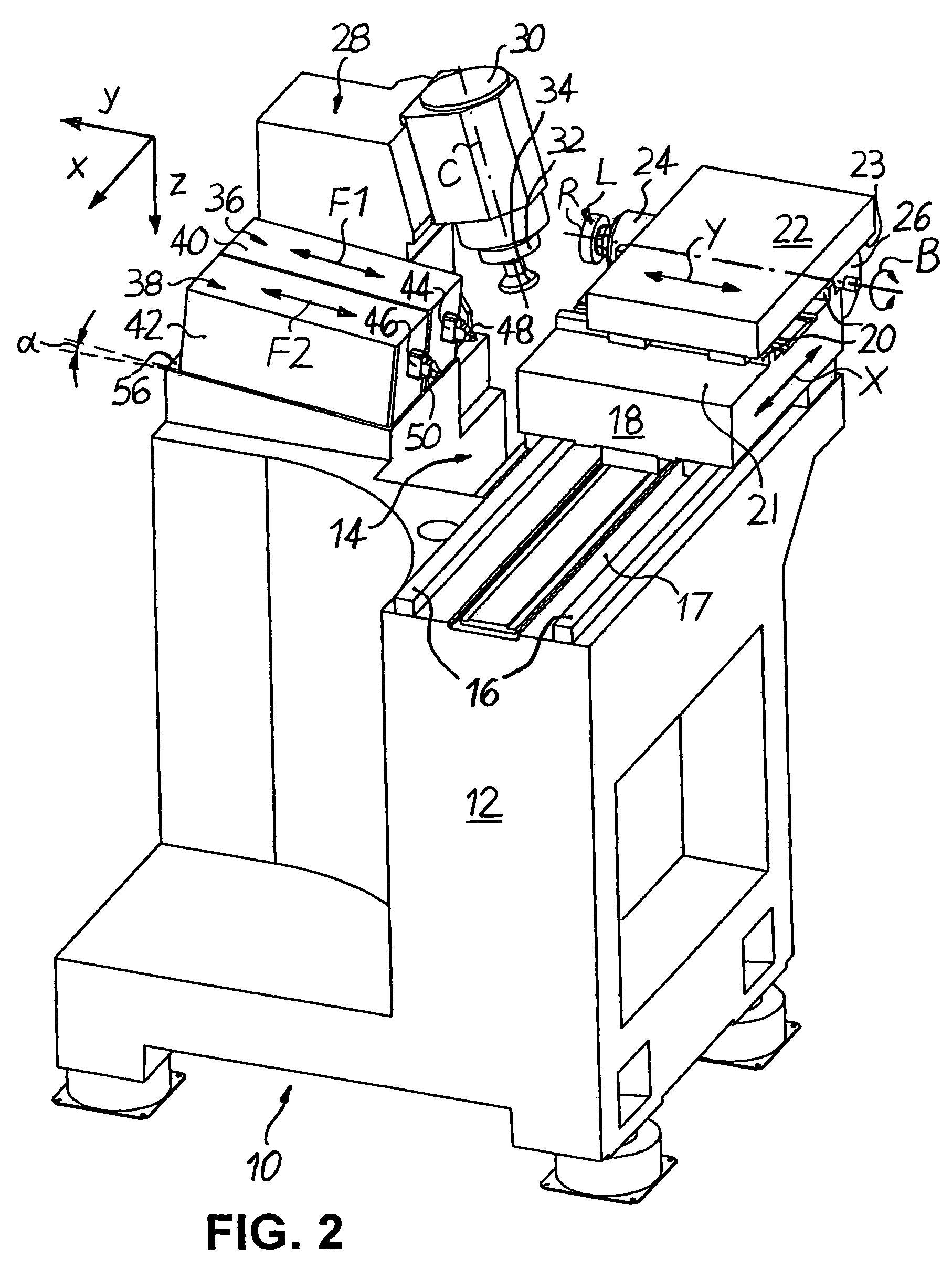
[0022]FIGS. 1 to 5 schematically show a CNC-controlled machine 10 in particular for machining surfaces of spectacle lenses L made of plastic in a right-angled Cartesian co-ordinate system, in which the letters x, y and z denote the width direction (x), the length direction (y) and the height direction (z) of the machine 10.

[0023]As shown in FIGS. 1 to 5, the machine 10 comprises a machine frame 12, which delimits a machining area 14. Fixed to the left-hand side of the machining area 14 in FIG. 1 are two guide rails 16 which extend parallel to one another in the (horizontal) width direction x, on an upper mounting surface 17 of the machine frame 12 in FIG. 1. Displaceably mounted on the guide rails 16 is an X-slide 18, which can be adjusted in a CNC positionally controlled manner in both directions of an X axis by associated CNC drive and control elements (not shown).

[0024]Two further guide rails 20, which extend parallel to one another in the (likewise horizontal) length direction y...


PUM

PropertyMeasurementUnit
work angleaaaaaaaaaa
angleaaaaaaaaaa

Abstract

A machine for machining optical workpieces, in particular plastic spectacle lenses, which has a workpiece spindle, which drives the workpiece in rotation about a workpiece rotation axis (B), and a fast tool arrangement, which moves a turning tool in a fast tool movement plane (X-F1), wherein the workpiece spindle and the fast tool arrangement can moreover be moved relative to one another in a plane (X-Y) which contains the workpiece rotation axis (B). The fast tool movement plane (X-F1) is positioned obliquely (work angle α) with respect to the plane (X-Y) containing the workpiece rotation axis (B). As a result, a machine is provided in which the working point of the cutting edge of the turning tool can be aligned in a particularly simple and highly precise manner on the rotation axis (B) of the workpiece spindle.

Description

TECHNICAL FIELD[0001]The present invention relates to a machine for machining optical workpieces, in particular plastic spectacle lenses.PRIOR ART[0002]When machining plastic spectacle lenses, there is usually a spectacle lens “blank” which has been injection-molded from plastic and has a standardized machined convex outer surface with, for example, a spherical or progressive shape. Depending on the desired optical effect, the inner or prescription surfaces (usually concave) are given a spherical, aspherical, toric, atoric, progressive or free-form geometry (progressive lens surfaces) by means of cutting machining. The typical conventional procedure when machining inner surfaces provides that, once the spectacle lens blank has been placed with its outer surface on a block, a cutting or turning machining process is carried out to produce the optically active shape, usually followed by a fine grinding or polishing process to achieve the necessary surface quality.[0003]For the abovemen...

Claims


Application Information

Patent Timeline
Patent Type & Authority Patents(United States)
IPC IPC(8): B23B3/00
CPCB24B13/046B24B13/06B24B41/00B24B47/20B24B47/22Y10T82/2502B23Q2230/004Y10T82/10Y10T82/2541B23Q1/60B29D11/00942
Inventor SAVOIE, MARCMCPHERSON, EDWARD
Owner SATISLOH GMBH
Why Eureka
Try Eureka