Reed's high-rise emergency rescue egress system

a high-rise, emergency rescue technology, applied in the direction of building support scaffolds, construction, building aids, etc., can solve the problems of limited municipal liability, no efficient and safe emergency service system for fire departments, and low operating cos

Inactive Publication Date: 2009-10-06
REED WAYMON BURTON
View PDF4 Cites 8 Cited by
  • Summary
  • Abstract
  • Description
  • Claims
  • Application Information

AI Technical Summary

Benefits of technology

[0015]The body is mounted to the rear frame of the high-rise emergency rescue vehicle and is equipped with an electric generator that is powered by the vehicle's transmission power take off. The body is outfitted with a turn-table frame and an electric / hydraulic system that extends the frame for positioning the gondola, in or out. The body is equipped with an electric / hydraulic driven system that maneuvers a platform up or down for positioning the gondola. The body is also furnished with a continuous self leveling component for maintaining unit balance and an electric / hydraulic driven outriggers system for system stability. The body is constructed using a frame extension which moves in and out and a rear adjustable platform which raises and lowers the Gondola. The body, above the control room, is fitted with spot lights, emergency flashing lights and antennas. The body also has a control room, draw-works section and transports the gondola and block.

Problems solved by technology

Regarding emergency rescue and evacuation, fire departments have no efficient and safe systems with which to service emergencies above the reach of ladder trucks.
The use of this high-rise system would result in lower operating cost and limited municipal liability caused by fires, earthquakes, terrorist attacks or other high-rise emergencies.
The prior art demonstrated by Mr. Catalan would allow users to be overcome by smoke inhalation due to the fact the interior structure of the descending chute apparatus is designed similar to a chimney or flue structure plan and could possibly cause such a system to draw or pull smoke inward, and upward, thus, causing injury or death to the occupants.
Further, emergency responders have limited access to the upper floors due in part to the downward spiral of Mr. Catalan's emergency evacuation system.
It should also be noted that such a system would be limited to stability and movement around the face of a high-rise building.
Most high-rise building codes will not allow weight to be placed on the upper, exterior wall structure of a high-rise building. Mr. Kucher's high-rise evacuation system could be restricted because of wind currents and positioning outside the walls of a high-rise building.
Another disadvantage may be the lack of roof access abilities for the emergency responders.
Most firemen and firefighters are reluctant to use fire fighting equipment that may be operated by people other than their fire fighting factuality. Mr. Kucher's prior art describing his emergency evacuation invention does not afford firemen the choice for operating such a system.
A movable chute evacuation system such as Mr. Chen's is limited because of different size and shape high-rise buildings and window openings for access and egress.
The configuration of this type of evacuation system would not be cost effective for the building owners and might be hazardous for those who elected to use such a system.
None of the prior art devices, however, have met this requirement.

Method used


Image

  • Reed's high-rise emergency rescue egress system
  • Reed's high-rise emergency rescue egress system
  • Reed's high-rise emergency rescue egress system

Examples


Embodiment Construction

[0045]A more detailed understanding of the present invention may be had by reference to the following detailed description when taken in conjunction with the drawings wherein:

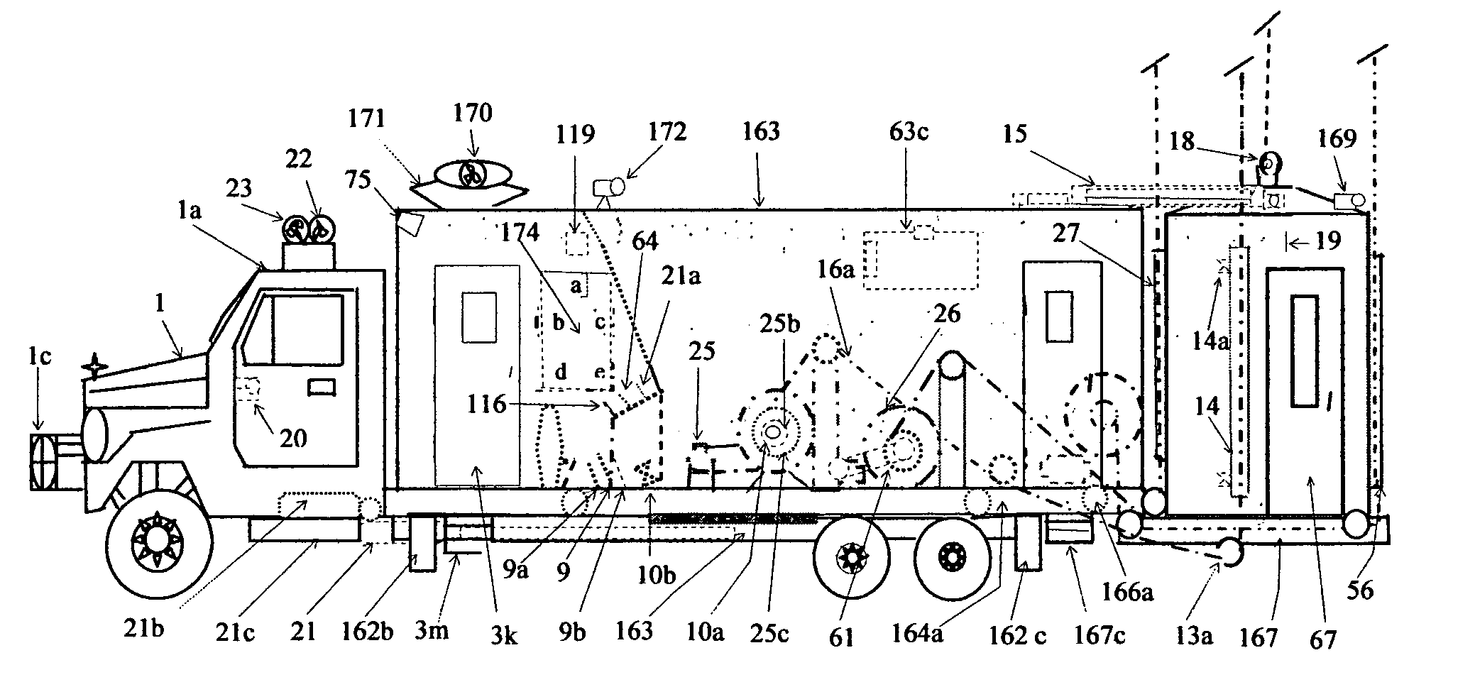
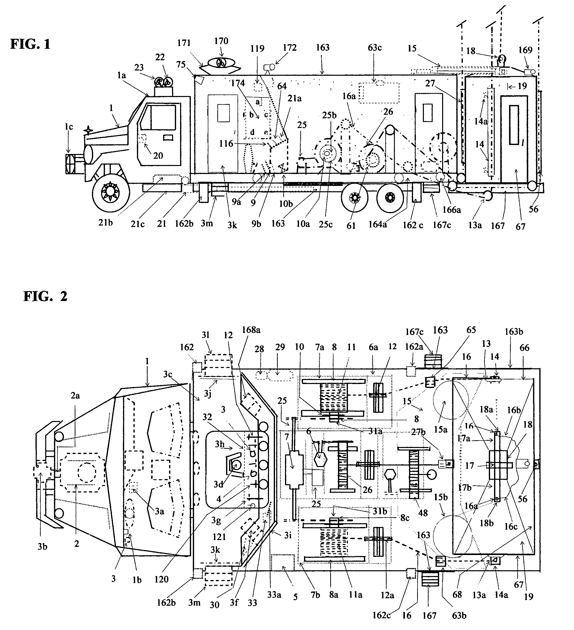
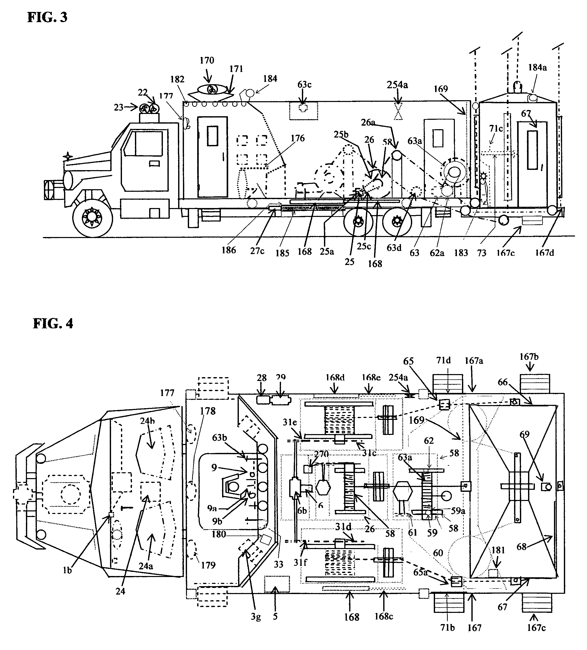
[0046]FIGS. 1, 2, 3 and 4—Vehicle:

[0047]The vehicle 1 is a large commercial truck with an extended rear frame that is custom designed using a turn-table frame for positioning and hydraulic outriggers for stabilization. The vehicle consists of four areas, each performing different functions:

[0048]Vehicle 1 and cab 1a houses all the electric and hydraulic controls necessary for operating the high-rise emergency rescue egress system. All operational switches to operate the communication and emergency lights 22 and sirens 23 are located on a console 24 mounted between the vehicle 1, cab 1a, driver seat 24a and passenger seat 24b. The ignition switch 1b and other hydraulic controls, and kill switches, are located on the dashboard inside cab 1a. When actual emergency operations begin all controls and functions are tr...


PUM


Abstract

Reed's High-Rise Emergency Rescue Egress System, a conventional truck chassis fitted with a hydraulic lift system for access into and the evacuation of individuals from high-rise buildings. The technology is comprised of the following components: A control room located behind the cab of the truck, which is used to operate the lift system, monitor system operations, detect chemical, radiological, biological or other hazardous agents, and provides communication support; an gondola cabins which provides protection while transporting personnel and equipment up and down. The gondola has the ability to be connected to a building's internal / external water stand-pipe system to allow hoses to be used directly from the cabin and an audio / video monitoring system that transmits information to the control room; a mechanical lift system, which utilizes hydraulic and electrical lifts. The lift system is powered by the vehicle's motor. The lift system is augmented by an electrical / hydraulic turntable frame that maneuvers a platform containing the gondola cabin and allows for the gondola cabin to be extended and retracted, raised and lowered. Additionally, buildings can have an optional fixed or portable cantilever system that also aids in the movement of the cabin. The ground rescue vehicle and the roof cantilever system may move vertically simultaneously.

Description

CROSS-REFERENCE TO RELATED APPLICATIONS[0001]This application is a continuation of Provisional Patent Application No. 60 / 555,998 filed Mar. 24, 2004 and Provisional Patent Application No. 60 / 614,539 filed Sep. 30, 2004.STATEMENT REGARDING FEDERALLY SPONSORED RESEARCH OR DEVELOPMENT[0002]Not applicable.REFERENCE TO A MICROFICHE APPENDIX[0003]Not applicable.BACKGROUND OF THE INVENTION[0004]Regarding emergency rescue and evacuation, fire departments have no efficient and safe systems with which to service emergencies above the reach of ladder trucks. Reed's High-Rise Emergency Rescue Egress System would provide quicker access to the crisis and a safe escape for emergency responders and the inhabitants occupying a high-rise building during a disaster.[0005]The use of this high-rise system would result in lower operating cost and limited municipal liability caused by fires, earthquakes, terrorist attacks or other high-rise emergencies. Those who will benefit from the cost efficient syste...

Claims


Application Information

Patent Timeline
Patent Type & Authority Patents(United States)
IPC IPC(8): E04G3/28
CPCA62B1/02
Inventor REED, WAYMON BURTON
Owner REED WAYMON BURTON
Why Eureka
Try Eureka