
Electric traction

a technology of electric traction and drive train, which is applied in the direction of electric propulsion mounting, battery/fuel cell control arrangement, transportation and packaging, etc., can solve the problems of uneconomical feasible alternative, large heat, noise and exhaust emissions, and undesirable use of ice in some ways,

Active Publication Date: 2009-10-13
AKIN RICK
View PDF206 Cites 59 Cited by
  • Summary
  • Abstract
  • Description
  • Claims
  • Application Information

AI Technical Summary

Benefits of technology

Reduces fuel consumption and emissions by enabling electric traction in trucks, even when idling or moving slowly, without the need for transmission replacement and with minimal power loss, suitable for heavy loads and urban environments.

Problems solved by technology

This use of ICE's is in some ways undesirable.
The fuel usage and emissions of heat, noise and exhaust in these situations are very large relative to the distances that loads are moved.
However, an economically feasible alternative has not been developed, particularly for loads handled by heavy duty, tractor-trailer trucks.
There are, however, numerous obstacles to the use of electric motors, particularly for applications such as described above for trucks.
Even with regard to merely this one obstacle, the teachings of Schmidt may be of limited use for the problem described herein above and similar problems.
Since there are a multitude of trucks currently in service, this approach does not provide a practical transition to the use of electric motors for this service.
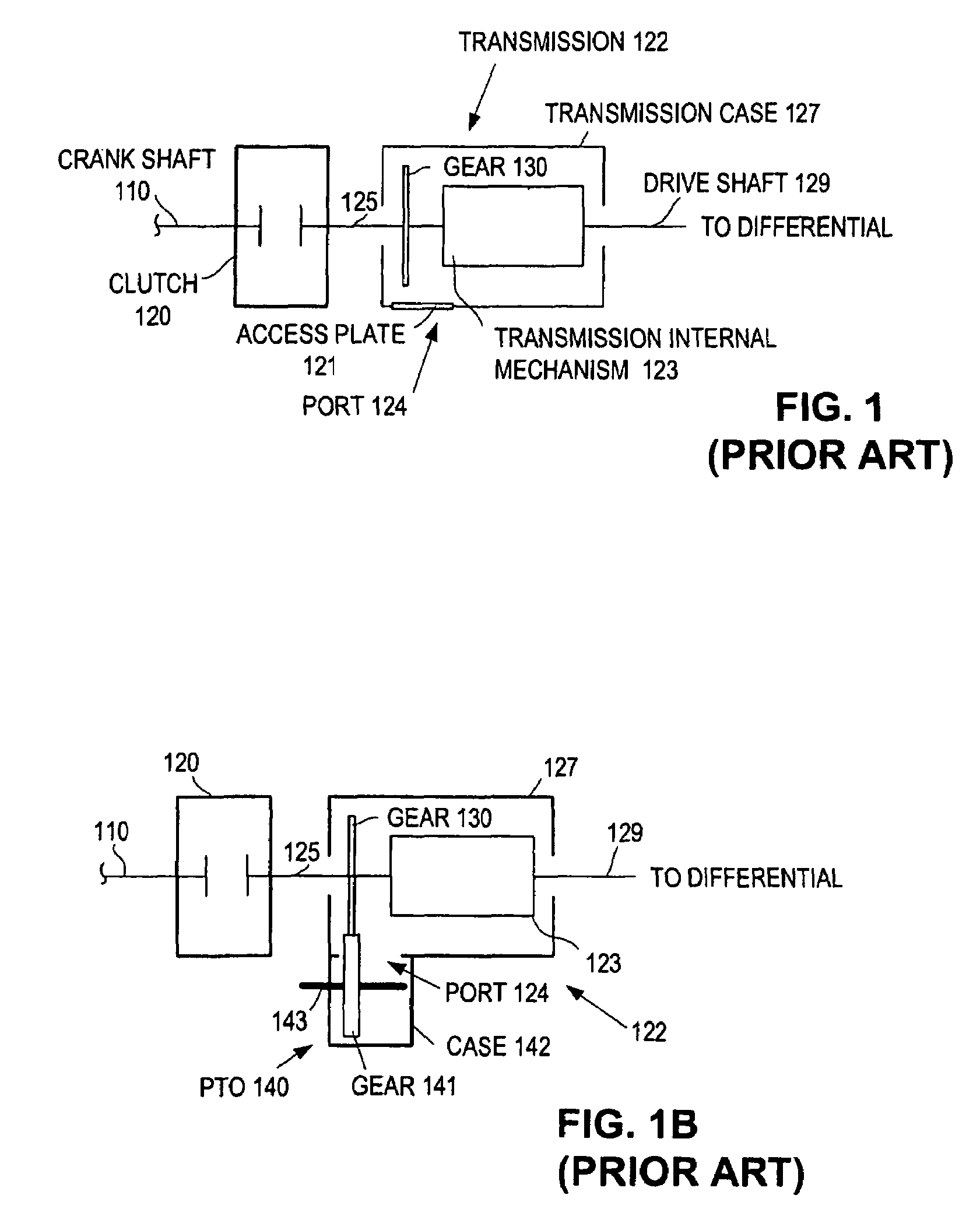
While this arrangement does not require replacement of the vehicle's original transmission, it has other disadvantages, not the least of which is that the ICE operates full-time in order to supply power to the PTO for inching.
Also, power losses through the hydraulic pump, hydraulic motor and secondary transmission are substantial.
As in the teachings of Ohke, Jedrzykowski's disclosure only addresses a limited set of obstacles with regard to the present problem and also has the disadvantage that operation of the ICE ultimately supplies the power for creeping, so that the ICE must operate full time.

Method used


Image

  • Electric traction
  • Electric traction
  • Electric traction

Examples


Embodiment Construction

[0039]In the following detailed description of the preferred embodiments, reference is made to the accompanying drawings illustrating embodiments in which the invention may be practiced. It should be understood that other embodiments may be utilized and changes may be made without departing from the scope of the present invention. The drawings and detailed description are not intended to limit the invention to the particular form disclosed. On the contrary, the intention is to cover all modifications, equivalents and alternatives falling within the spirit and scope of the present invention as defined by the appended claims. Headings herein are not intended to limit the subject matter in any way.

[0040]Overview

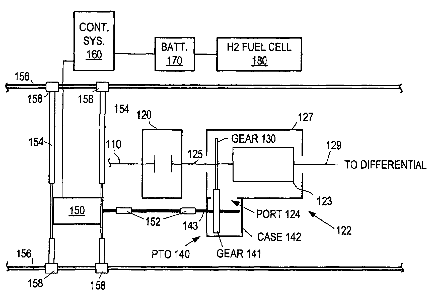
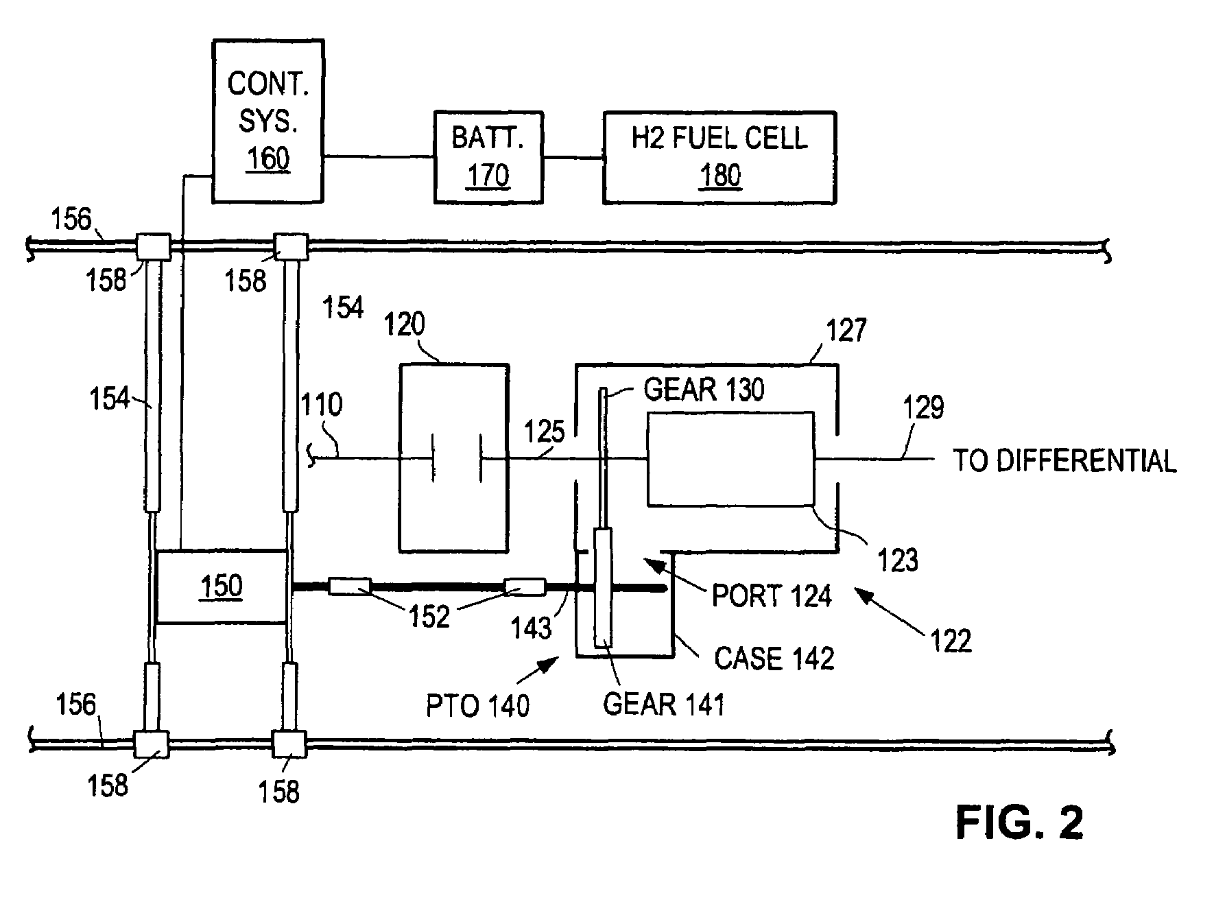
[0041]According to an embodiment of the present invention, an electric traction system includes an electric motor (referred to herein also as an electric traction motor) to drive a vehicle's conventional or original equipment transmission for traction when the vehicle is moving ...


PUM


Abstract

A drive train includes an internal combustion engine (“ICE”) coupled to a transmission having a power takeoff port. A transfer device couples an electric motor to the transmission via the port. The electric motor is enabled in a certain configuration to selectively power the drive train during at least certain intervals when the ICE is powered off.

Description

RELATED APPLICATIONS[0001]This is a nonprovisional application claiming the benefit of the priority date of Warner Olan Harris, U.S. provisional application No. 60 / 774,732, filed Feb. 21, 2006, entitled “Hybrid electric traction power system for moving class 7&8 tractors by means of a drive motor attached to the power takeoff (PTO) of the tractor's transmission PTO connection point,” which is hereby incorporated herein by reference.[0002]This is also a continuation-in-part application claiming the benefit of the priority date of Warner Olan Harris, U.S. nonprovisional patent application Ser. No. 11 / 374,709, filed Mar. 14, 2006, entitled “Fuel cell-driven auxiliary system, and method therefor,” which claims the benefit of the priority date of Warner Olan Harris, U.S. provisional patent application No. 60 / 661,668 filed Mar. 14, 2005, which are hereby incorporated herein by reference.BACKGROUND[0003]1. Field of the Invention[0004]The present invention concerns a drive train including a...

Claims


Application Information

Patent Timeline
Patent Type & Authority Patents(United States)
IPC IPC(8): B60K1/00B60K6/48B60K6/547B60L50/15B60L50/16
CPCB60K6/32B60K6/48B60K6/547B60K17/28B60L11/14B60L11/1868B60L11/1881B60L11/1887B60L11/1892B60L15/2045B60L2240/421Y02T10/70B60L2270/145B60Y2200/14Y02T10/6221Y02T10/642Y02T10/7077Y02T90/34B60L2240/12Y02T10/7066Y02T10/7283B60L2250/16Y02T10/72B60L50/16B60L58/20B60L58/30B60L58/40B60L58/33Y02T10/62Y02T10/64Y02T10/7072Y02T90/40B60K6/50B60K6/20
Inventor HARRIS, WARNER OLAN
Owner AKIN RICK
Learn More