Supply architecture for inductive loads

Inactive Publication Date: 2009-10-13
FLYBACK ENERGY
View PDF39 Cites 12 Cited by
  • Summary
  • Abstract
  • Description
  • Claims
  • Application Information

AI Technical Summary

Problems solved by technology

Second, energy may be supplied to th

Method used


Image

  • Supply architecture for inductive loads
  • Supply architecture for inductive loads
  • Supply architecture for inductive loads

Examples


Embodiment Construction

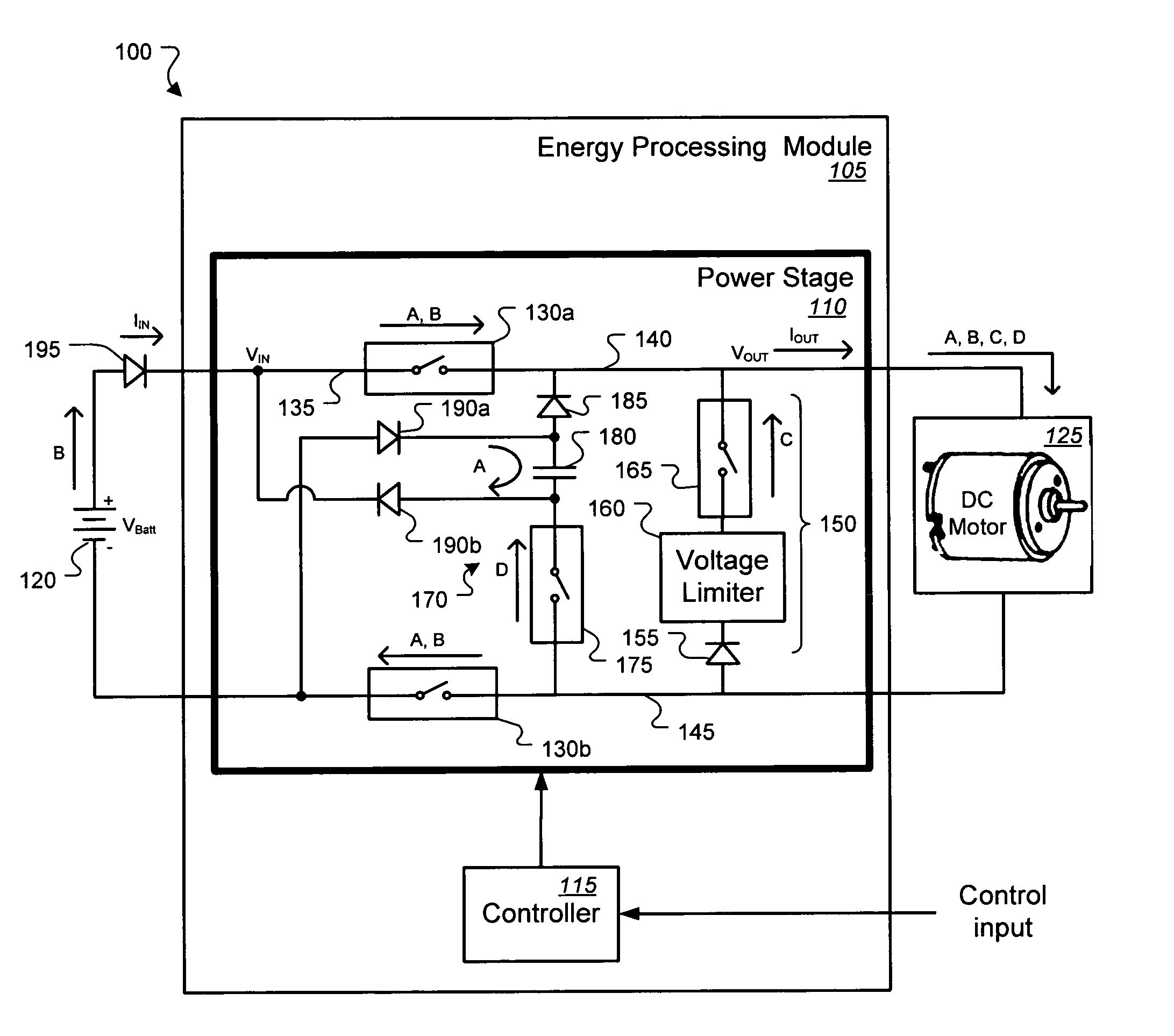
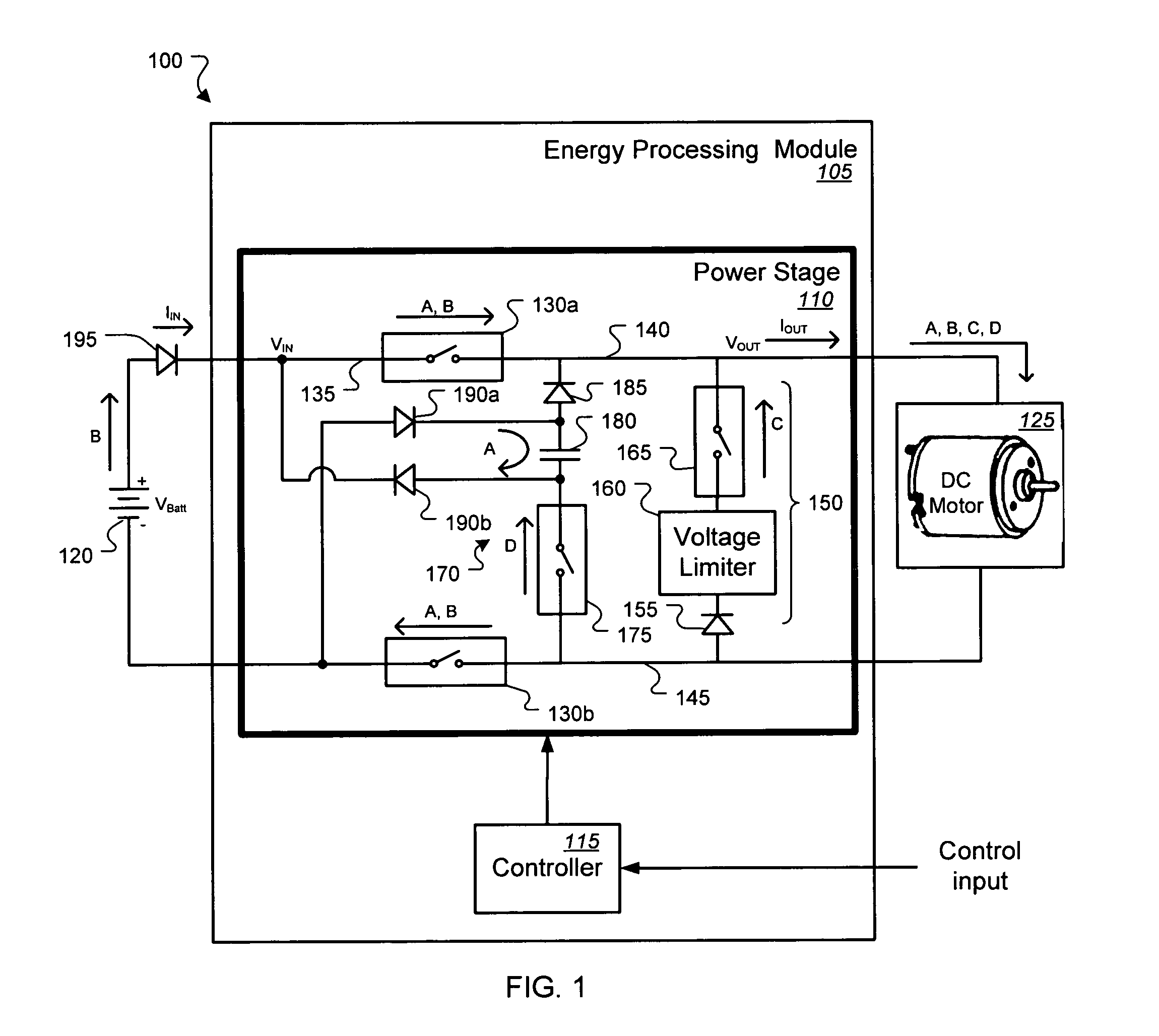
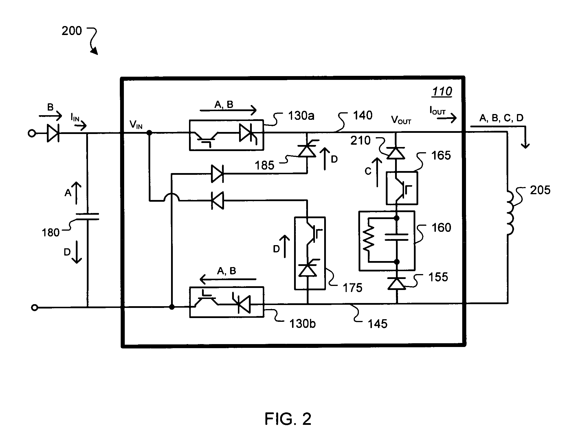
[0021]FIG. 1 shows an exemplary system 100 in which energy may be supplied to inductive and / or resistive loads at a controllable rate with high efficiency and low electromagnetic noise. The system 100 of this example includes an energy processing module 105 that receives energy at an input, processes the energy, and delivers unidirectional current to supply energy to a load connected at an output. The module 105 includes a power stage 110 that operates in response to control signals from a controller 115. In operation, the controller 115 controls the operating states of switches in the power stage 110 according to a sequence of operating states that may, for example, be repeated in a cyclical pattern. In an exemplary cycle of operation, the controller 115 generates a sequence of operating states that cause the power stage 110 to store energy from a power source 120 into an inductive load 125, control a reverse electromotive force (REMF) that may develop when the inductive load 125 i...


PUM


Abstract

Apparatus and associated systems and methods may relate to a process for supplying unidirectional current to a load, controlling a reverse electromotive force (REMF), capturing inductive energy from the load, and supplying the captured inductive energy to the load. In an illustrative example, an operating cycle may include a sequence of operations. First, inductive energy captured from the load on a previous cycle may be supplied to the load. Second, energy may be supplied to the load from an external power source. Third, a REMF voltage may be substantially controlled upon disconnecting the power source from the load. Fourth, the load current may be brought to zero by capturing the inductive energy for use on a subsequent cycle. In some embodiments, a single power stage may supply a DC inductive load, or a pair of power stages may be operated to supply bidirectional current to an AC load.

Description

CROSS-REFERENCE TO RELATED APPLICATIONS[0001]This application claims priority under 35 USC §119 to U.S. patent application Ser. No. 60 / 754,460, entitled “Apparatus And Method For Improving Electromagnetic Processes By Capturing, Controlling and Utilizing Reverse EMF Energy,” which was filed on Dec. 28, 2005 by Babcock et al.TECHNICAL FIELD[0002]Various embodiments relate to operating inductive and / or resistive loads.BACKGROUND[0003]Many electrically-operated systems and devices have inductance. Some inductive devices, such as DC (direct current) motors, automotive ignition systems, and some electromagnets, can operate when supplied with a unidirectional current. Some inductive devices, such as transformers, AC (alternating current) motors, and fluorescent lights, operate when supplied with a bidirectional current.[0004]In general, inductive elements can store energy in a magnetic field. Typically, the magnetic field is supported by an electric current flowing through the inductive e...

Claims


Application Information

Patent Timeline
IPC IPC(8): G05F1/10H02H7/09
CPCH02P7/281
Inventor BABCOCK, PAUL M.BABCOCK, DAVID J.SMITH, PHILLIP N.
Owner FLYBACK ENERGY
Why Eureka
Try Eureka