
Voltage multiplier with improved efficiency

a voltage multiplier and efficiency technology, applied in the field of integrated circuits, can solve problems such as reducing the amount of charge transferred, affecting the output voltage of the voltage multiplier circuit, and reducing the threshold voltag

Inactive Publication Date: 2009-10-13
NORTH STAR INNOVATIONS
View PDF4 Cites 41 Cited by
  • Summary
  • Abstract
  • Description
  • Claims
  • Application Information

AI Technical Summary

Benefits of technology

The solution enhances power transfer efficiency, allows higher clock frequencies, reduces component count, and minimizes current loss, resulting in improved efficiency and extended battery life while maintaining a stable output voltage.

Problems solved by technology

Such variations in the voltage multiplier circuit output voltage can be problematic, particularly when the voltage multiplier circuit is used to drive circuits sensitive to supply voltage variations.
Another drawback with conventional voltage multiplier circuits is that the threshold voltage of the pass gate transistor can reduce the amount of charge transferred to the charge pump output, particularly when the pass gate transistor is not fully turned on.
Attempts to address this problem can lead to other problems, such as current return during non-aligned clock transitions and / or latch up that occurs if the well bias of p-channel MOS (PMOS) transistors (in a p-substrate process) is not in reverse-bias condition.
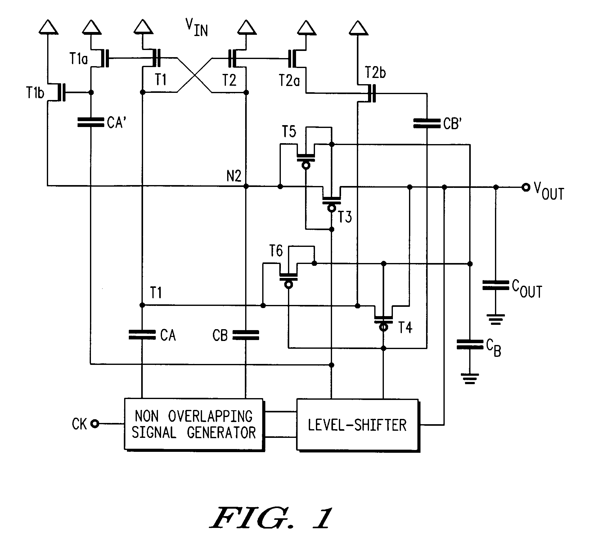
In addition, the dual series switches T3, T4 do not block reverse current that can be caused when the non-overlapping clocks are skewed, setting an upper limit to the practical maximum clock frequency and resulting in less efficient power transfer.

Method used


Image

  • Voltage multiplier with improved efficiency
  • Voltage multiplier with improved efficiency
  • Voltage multiplier with improved efficiency

Examples


Embodiment Construction

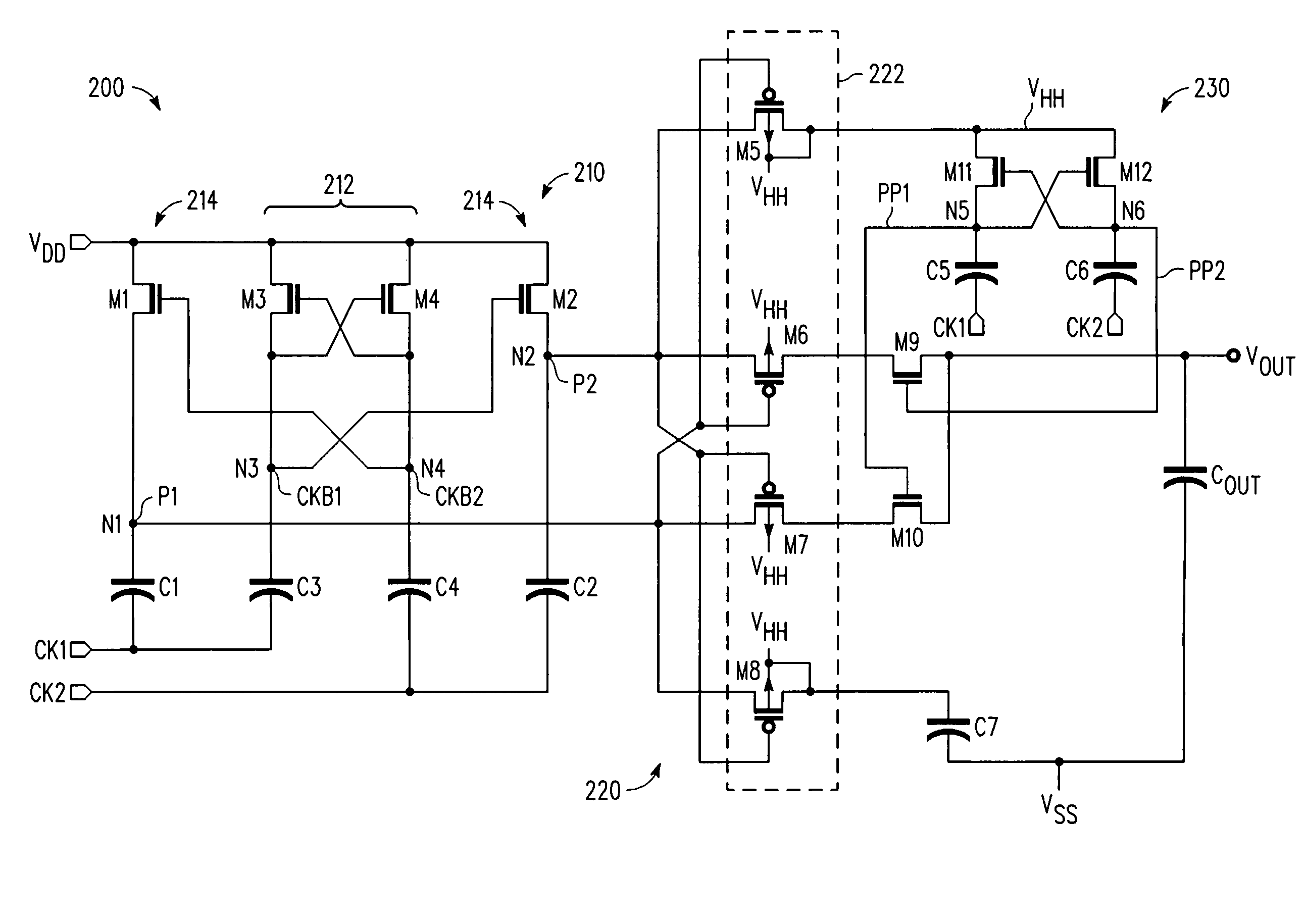
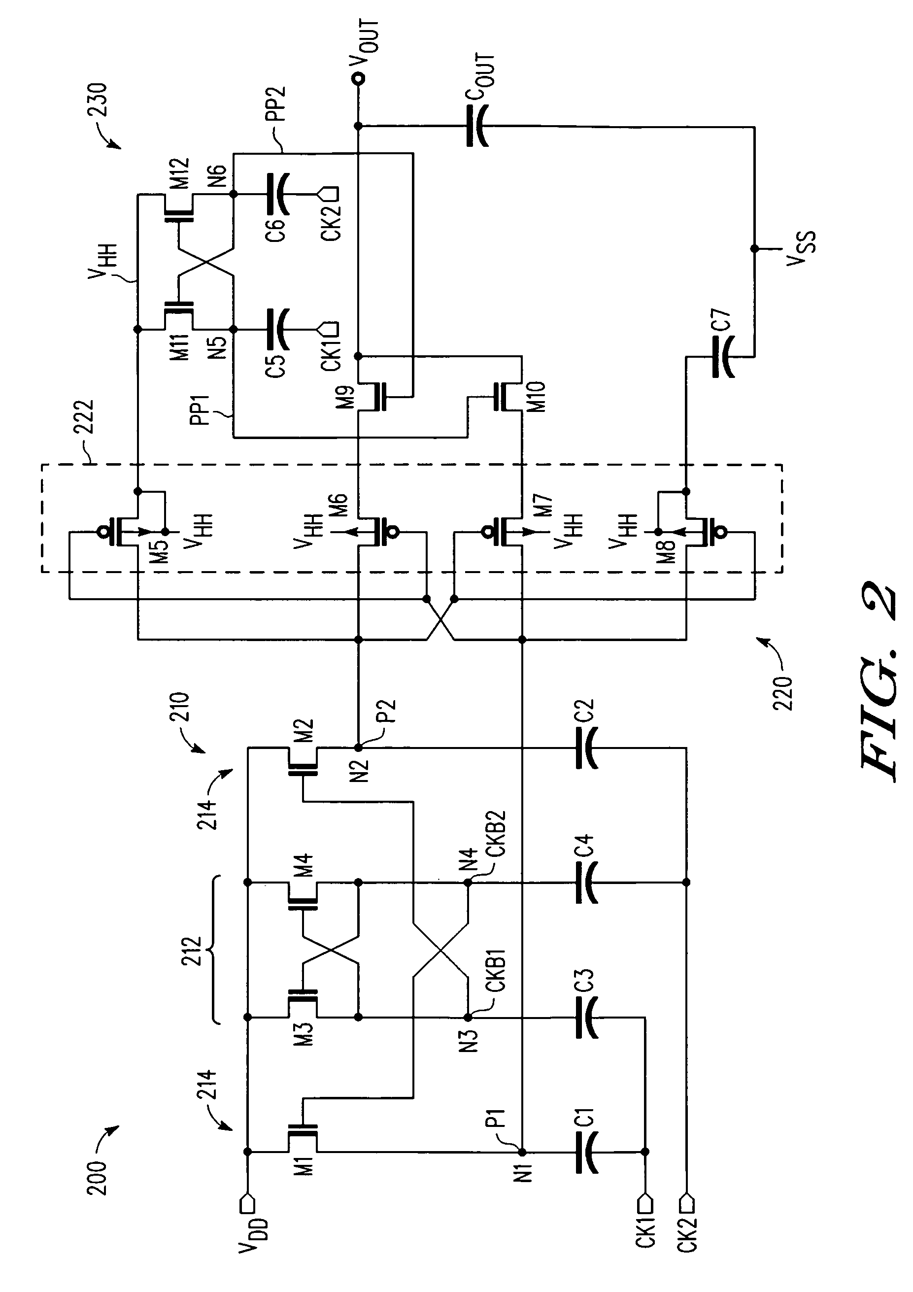
[0014]A multi-stage voltage multiplication circuit and methodology are described for use in integrated circuit applications to efficiently develop an output voltage that is higher than the input supply voltage. In selected embodiments, a two-stage complementary switch is used to connect boosted clock signals from a charge pump to the multiplier output in which the complementary switches are separately clocked. With the two-stage complementary switch, return current from the storage capacitor to the pumping capacitor is blocked, thereby increasing power transfer efficiency, even at high clock frequencies when clock skews are particularly harmful to converter efficiency. In general terms, the multi-stage voltage multiplier circuit includes a booster circuit that is clocked by non-overlapping clock inputs, and a pass gate circuit that selectively couples the booster circuit to the voltage multiplier output while preventing current return. The booster circuit may be implemented with two...


PUM


Abstract

A multi-stage voltage multiplication circuit and methodology are provided which use a multi-stage charge pump boosting circuit (210) and two-stage pass gate circuit (220) having complementary power switches (M6, M9, M7, M10) to efficiently develop an output voltage (VOUT) that is higher than the input supply voltage (VDD). By using a two-stage complementary switch to connect boosted clock signals (P1, P2) from a charge pump (210) to the multiplier output (VOUT), return current from the storage capacitor (COUT) to the pumping capacitor (C1, C2) is blocked, thereby increasing power transfer efficiency, even at high clock frequencies. In addition, a boosted auxiliary voltage is generated by an additional boosting stage (230) and applied to the PMOS wells of the pass gate circuit (220), thereby preventing latch-up and backflow.

Description

BACKGROUND OF THE INVENTION[0001]1. Field of the Invention[0002]The present invention is directed in general to the field of integrated circuits. In one aspect, the present invention relates to a voltage multiplier charge pump circuit.[0003]2. Description of the Related Art[0004]To provide a desired voltage output to a particular load, charge pumps are used to deliver a higher voltage than that provided by the power supply. Typically, a charge pump circuit receives two fixed input voltages, one of the input voltages being the power supply voltage (e.g., for example from a normal 1.5V battery) and the other being a clock voltage. A booster circuit receives the input voltages and produce a higher voltage on a capacitor, while a pass gate connects the charge on capacitor of the booster circuit to an output load which includes a load capacitance to smooth the resulting voltage. When configured as a voltage multiplier, the charge pump provides a nominal output voltage that is a multiple ...

Claims


Application Information

Patent Timeline
Patent Type & Authority Patents(United States)
IPC IPC(8): G05F1/10G05F3/02
CPCH02M3/073H02M2003/078H02M3/078
Inventor PIETRI, STEFANODE GOES, MARCOS AUGUSTOBERTOLI, ROBERTO ANGELO
Owner NORTH STAR INNOVATIONS
Learn More