Sensor for measuring the surface of an object

a sensor and object technology, applied in the direction of measuring devices, instruments, using optical means, etc., can solve the problems of large structural shape, jarring, and known sensors that react sensitively to jarring, and achieve excellent optical quality of the sensor, stable temperature behavior

Active Publication Date: 2009-10-13
ISRA VISION SYST AG
View PDF10 Cites 5 Cited by
  • Summary
  • Abstract
  • Description
  • Claims
  • Application Information

AI Technical Summary

Benefits of technology

[0005]The object of the invention is therefore to propose a sensor of the type defined at the outset which is compact in construction and robust in use and makes high precision in measurement possible.
[0006]This object is attained in a sensor of the type defined at the outset with the characteristics of claim 1, essentially that the contrasting unit has an LED projector. LEDs (light emitting diodes) can be triggered, in comparison to a laser, by less-complicated electronics, which according to the invention can be integrated with the sensor, and they are furthermore less expensive. LEDs are invulnerable to jarring and temperature fluctuations, and the generated light is not so dangerous to the human eye. By the use of an LED projector, a small, flexibly usable sensor for surface measurement is accordingly created which is capable for instance also of being mounted on a robot, with the loads involved in such a situation. Moreover, the camera and the LED projector are located in a longitudinal arrangement in the sensor housing. This housing therefore has only a low structural height and depth and is somewhat rectangular in cross section. In order to project the projection image out of the housing and record its image on the object, the camera and the projector are each assigned deflecting mirrors, which are located on opposite ends in the longitudinal direction of the sensor and which catch the projection image from the sensor and focus its recorded image into the sensor. Since the optical axes of the projection and the image recording in this arrangement have the greatest possible spacing apart, the outcome of measurement has the greatest possible precision.

Problems solved by technology

A disadvantage of the previously known sensors is that because of the laser for generating the contrast stripe, they have a large structural shape.
Moreover, the laser light presents safety risks to humans located in the measurement region, if the laser light strikes the retina.
Moreover, lasers are sensitive optical devices, so that the known sensors react sensitively to jarring and taken all in all are not robust.
This makes for a tall sensor housing, which can easily collide with the vehicle to which it is affixed, or restricts the adjustment path thereof.
Because of this optical arrangement, however, precise measurement of the object is not possible.

Method used


Image

  • Sensor for measuring the surface of an object
  • Sensor for measuring the surface of an object
  • Sensor for measuring the surface of an object

Examples


Embodiment Construction

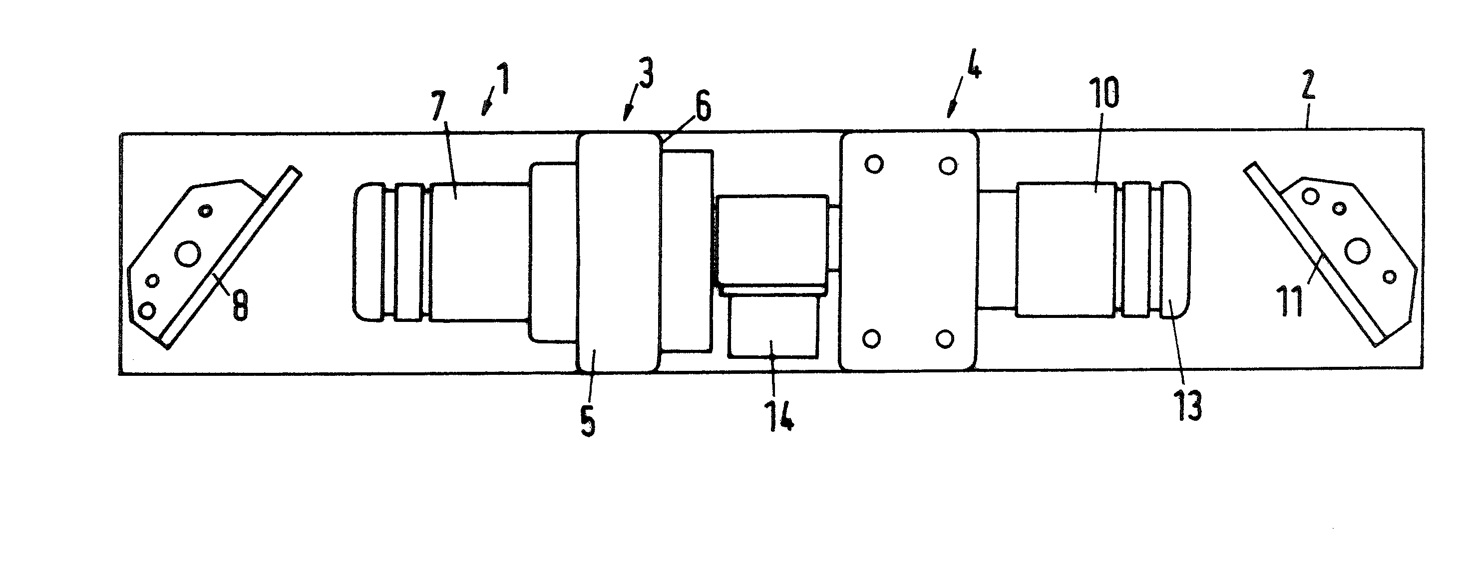
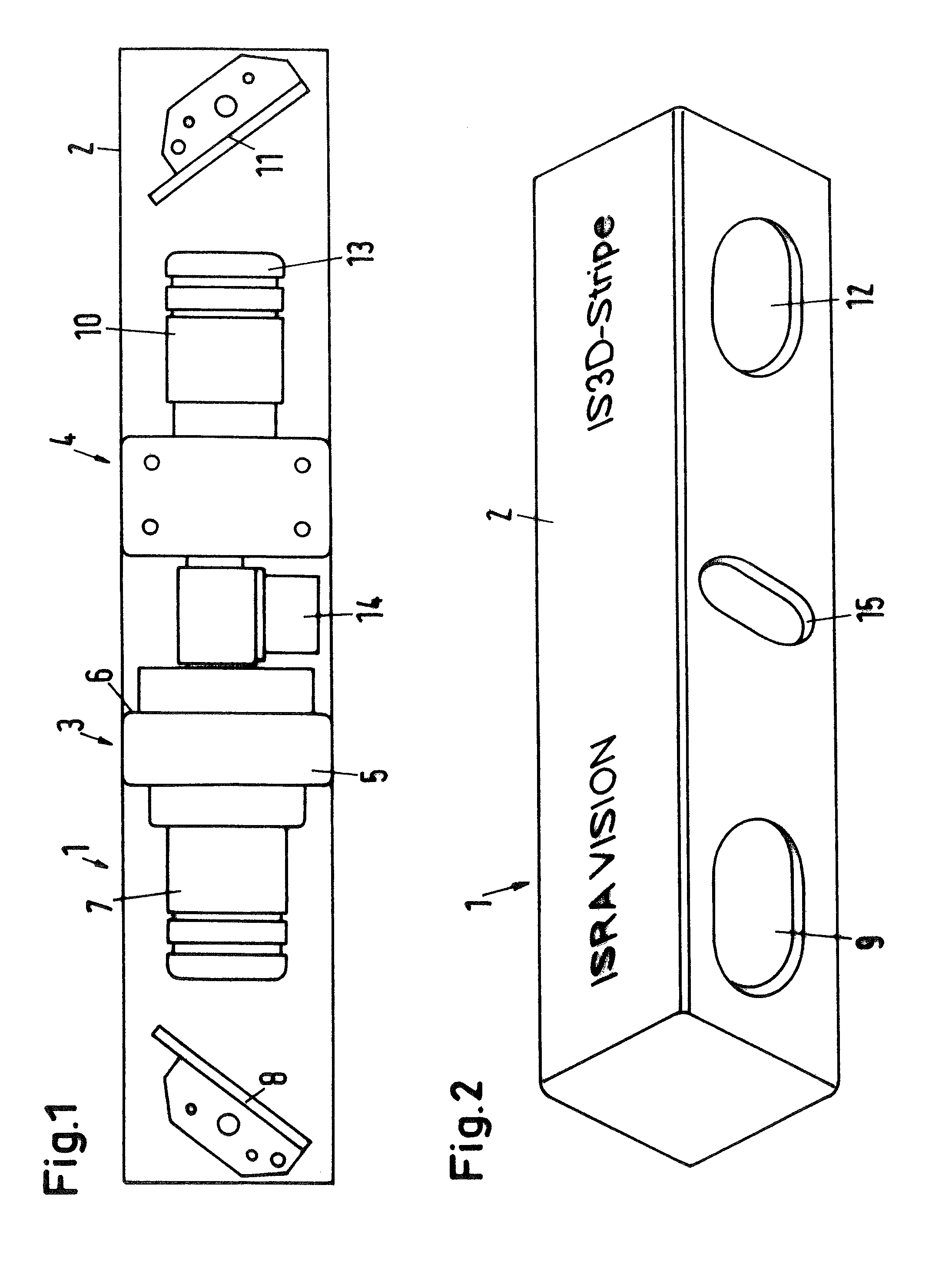
[0031]FIG. 1 shows the construction of a sensor 1 according to the invention for measuring the surface of an object in a housing 2. The sensor 1 has a contrasting unit 3 for projecting a pattern onto the surface of the object and also has a camera 4 for recording the pattern projected onto the surface of the object.

[0032]The contrasting unit 3 includes an LED projector 5, which generates a pattern that comprises a plurality of encoded stripes. To that end, a suitable LED and optics are received in the projector housing 6, which is closeable with a cap and is rotatable, and the projector housing 6 can be fixed in operation. For generating a projection image of the object surface to be measured, a lens system 7 is placed on the LED projector 5 and aimed at a deflecting mirror 8. The deflecting mirror 8 projects the projection image through a projection opening 9 (see FIG. 2) onto the surface to be measured of an object, not shown.

[0033]The projected image generated there is recorded b...


PUM


Abstract

The invention relates to a sensor for measuring the surface of an object, having a contrasting unit (3) for projecting a pattern onto the surface of the object, and having a camera (4) for recording of the pattern projected onto the surface of the object, in which the contrasting unit (3) has an LED projector (5). To achieve high precision and great robustness, the camera (4) and the LED projector (5) are located in the longitudinal direction. In addition, respective deflecting mirrors (8, 11) are assigned to the camera (4) and the LED projector (5) and are located on opposite ends, in the longitudinal direction of the sensor (1), of the housing (2) of the sensor (1).

Description

BACKGROUND OF THE INVENTION[0001]The invention relates to a sensor for measuring the surface of an object, having a contrasting unit for projecting a pattern onto the surface of the object, and having a camera for recording the pattern projected onto the surface of the object. This sensor, with an evaluation unit that can be connected to the sensor or integrated with the sensor, is especially suitable for the measurement principle of triangulation.[0002]Such sensors operating on the principle of triangulation are already known. They use lasers as a contrasting unit, and for contrast purposes they project a stripe onto the surface to be measured. This fundamental principle is known for instance from U.S. Pat. No. 6,256,099 B1 or from German Patent Disclosure DE 44 02 414 A1. By evaluating the stripe recorded by the camera, 3-dimensional points can be ascertained along a curve, which provide information about the surface structure. A disadvantage of the previously known sensors is tha...

Claims


Application Information

Patent Timeline
Patent Type & Authority Patents(United States)
IPC IPC(8): G01B11/24G01B11/25
CPCG01B11/25
Inventor ERSUE, ENISLAMBERT, GEORG
Owner ISRA VISION SYST AG
Why Eureka
Try Eureka