Eureka AIR delivers breakthrough ideas for toughest innovation challenges, trusted by R&D personnel around the world.

Audio packet switching system

Inactive Publication Date: 2009-10-13
LG ERICSSON
View PDF15 Cites 1 Cited by
  • Summary
  • Abstract
  • Description
  • Claims
  • Application Information

AI Technical Summary

Benefits of technology

[0017]It is another object of the present invention to more efficiently use system resources by making it easy to implement additional functions to the RTP and coder through a buffer.
[0019]The audio packet switching system of the preferred embodiment preferably provides a single RTP control interface for transmitting and receiving audio packets to manage overall system and raises a degree of resource utilization of the system by making it easy to implement additional functions to the RTP and coder through a buffer.
[0020]Additionally, the preferred embodiment enables an additional function that an audio mixer interfaces with a reception buffer without regard to the RTP to carry the mixed data to a reception buffer in order to be mixed with the other channel audio data. That function can be implemented by changing a binding of the transmission and reception buffers to change an audio packet router without any changes to the RTP setting.

Problems solved by technology

The RTP operations are limited to the operation of the RTP at both communication end points to transmit and receive the audio / video packets.
The related art switching system and method, however, has various problems.
For example, it is difficult to implement a system using various protocols and to manage overall network resources and source codes, because a hard coding method to the corresponding signaling protocol is used.
Since the operations of each protocol are accomplished through a predetermined interface with the RTP in the switching system implemented using the standard protocol, however, overall RTP management with the other protocols becomes difficult.
Additionally, operations of the audio coder also become difficult and implementation efficiency of additional functions is reduced.

Method used


Image

  • Audio packet switching system
  • Audio packet switching system
  • Audio packet switching system

Examples


Embodiment Construction

[0029]The following detailed description describes an audio packet switching system according to a preferred embodiment of the invention in reference to the accompanying drawings.

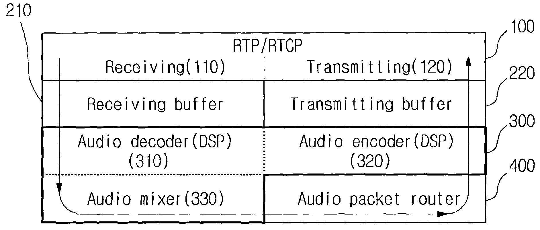
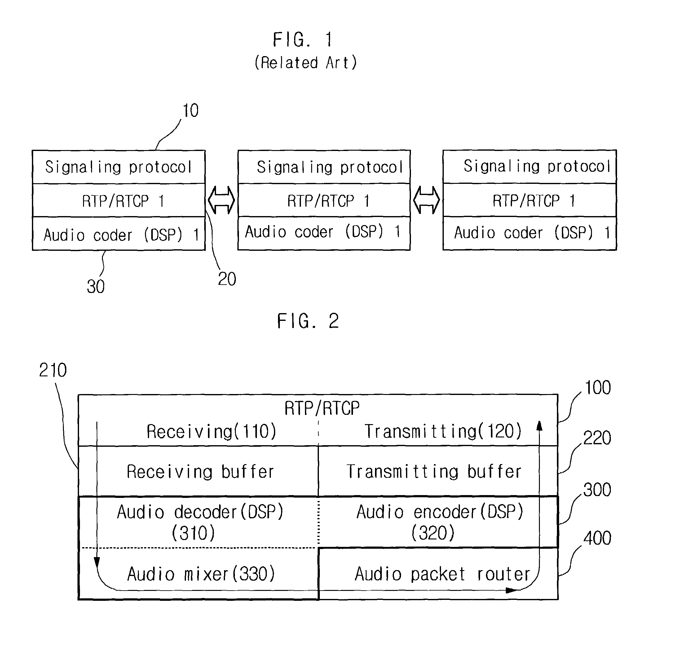
[0030]FIG. 2 is a block diagram illustrating an IP based audio packet switching system according to the preferred embodiment of the present invention. Although described herein with reference to audio packets, it should be understood that any type of packets, such as video packets, could be used.

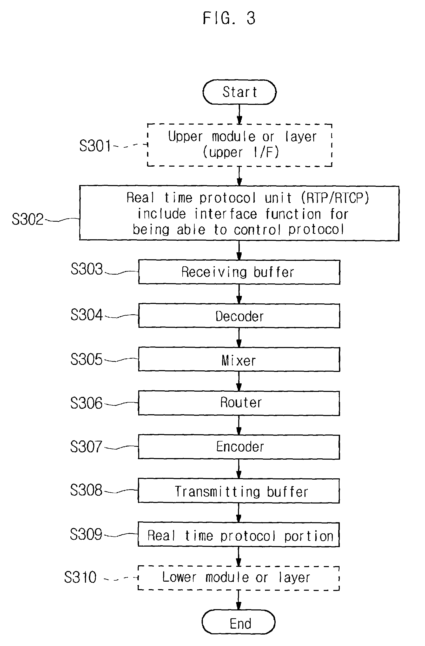
[0031]Referring to FIG. 2, the IP based audio packet switching system preferably includes a real time protocol unit 100 (RTP / RTCP module) including interface functions for performing RTP / RTCP and controls, and buffers 210 / 220 for correcting a transmission speed of audio data, which is transmitted and received irregularly from the real time protocol unit 100. The IP based audio packet switching system preferably further includes an audio coder unit 300 for compressing and recovering the audio data transmitted and rec...


PUM


Abstract

The present invention relates to an IP based or network based audio packet switching system, and more specifically to an audio packet switching system for integrating each independent module into a single interface for consistent control and data flow. Independent modules, such as a RTP / RTCP, encoder / decoder and mixer, are interworked with reception and transmission buffers to make a system more flexible. Additionally, audio data paths inside the switch are controlled through an audio packet router. The multi protocol system employing the RTP provides a single RTP control interface for transmitting and receiving audio packets to completely manage the system totally and raises a degree of resource utilization of the system by making it easy to implement additional functions to the RTP and coder through the buffers.

Description

BACKGROUND OF THE INVENTION[0001]1. Field of the Invention[0002]The present invention relates to a network based switching system, and more particularly to an audio packet switching system, operated as a single interface when various signaling protocols are introduced, for processing Real-time Transport Protocol (RTP) packet and audio data[0003]2. Background of the Related Art[0004]Real-time Transport Protocol (RTP) is a communication protocol of the transport layer for transmitting and receiving voice or motion pictures in real time. RTP is characterized in that communications are processed between terminals without depending on communication devices such as a router, etc.[0005]Generally, a system for transmitting audio data, such as IP based or network based switching system using the RTP protocol, employs a hard coding method according to a signaling protocol. Hard coding is a method that performs coding depending on the corresponding protocol.[0006]FIG. 1 is a block diagram illu...

Claims


Application Information

Patent Timeline
IPC IPC(8): H04L12/66H04L47/2416H04L47/30
CPCH04L29/06027H04L47/2416H04L65/608H04L47/30H04L65/607H04L47/263H04L65/70H04L65/65H04L2012/5603H04N21/6437H04L65/1101
Inventor LEE, SEOK WON
Owner LG ERICSSON
Why Eureka
Eureka Blog
Learn More