Network interface speed adjustment to accommodate high system latency in power savings mode

Active Publication Date: 2009-10-13
NVIDIA CORP
View PDF4 Cites 55 Cited by
  • Summary
  • Abstract
  • Description
  • Claims
  • Application Information

AI Technical Summary

Benefits of technology

[0009]In a power savings mode a speed setting of a network interface is reduced to accommodate increased system latency. In one embodiment of a computing system the network interface has at least two selectable network speed settings. A receive buffer buffers incoming data traffic received by the network interface with the receive buffer having a maximum buffer size for buffering incoming data without loss. A data receiving portion of a computing system receives incoming data from the buffer. The data receiving portion has a plurality of performance levels including a normal operating level and at least two power down levels with each power down level having a latency associated with a transition to a normal operat

Problems solved by technology

One problem with designing computing system 100 for “lossless” high-speed applications is that it limits the potential power-savings options that can be achieved in a cost-effective manner.
However, power savings modes reflect a tradeoff between power consumption and performance.
Typically, one tradeoff is a tradeoff between power consumption and system latency for performing memory accesses.
However, a

Method used


Image

  • Network interface speed adjustment to accommodate high system latency in power savings mode
  • Network interface speed adjustment to accommodate high system latency in power savings mode
  • Network interface speed adjustment to accommodate high system latency in power savings mode

Examples


Embodiment Construction

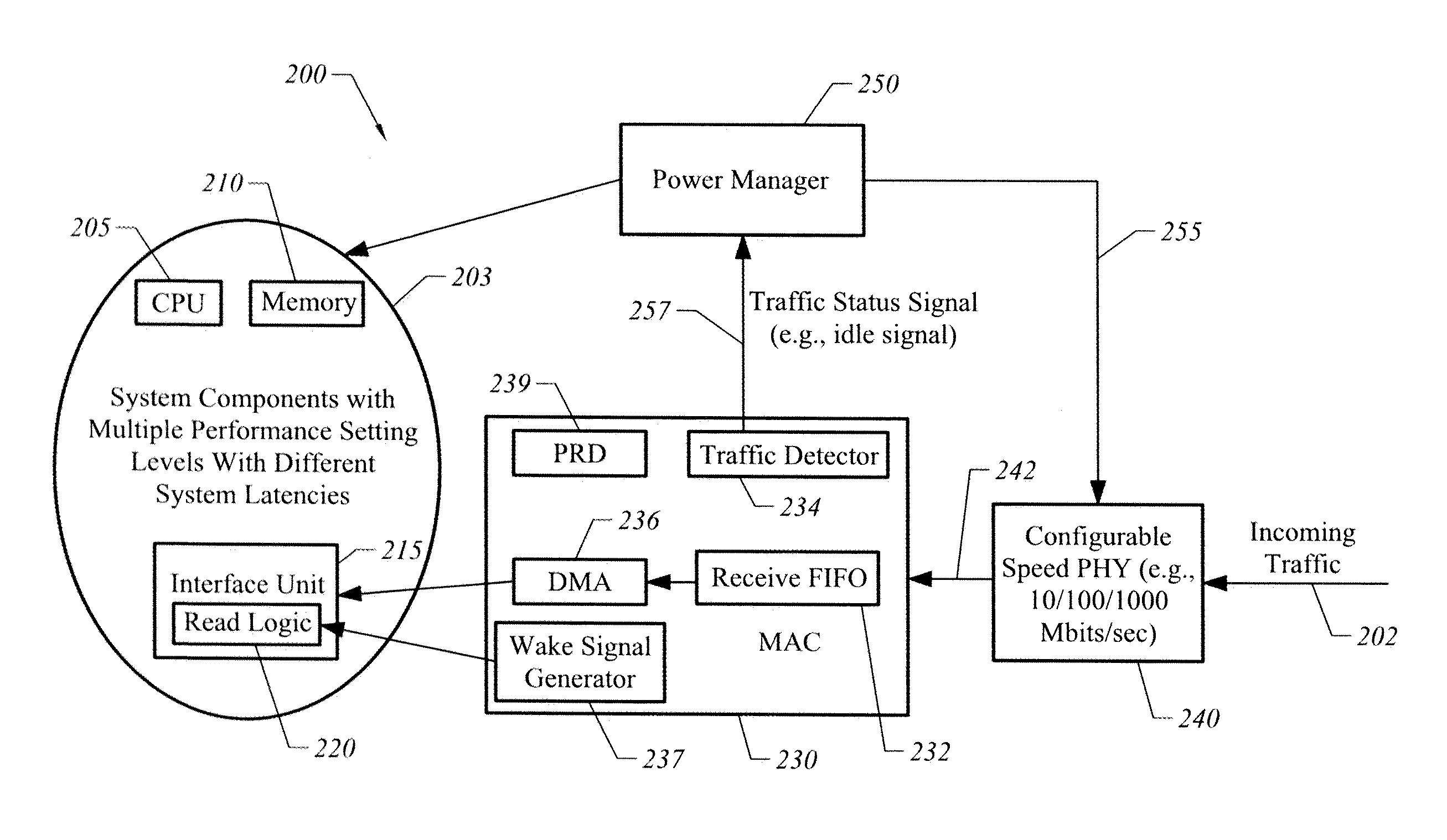
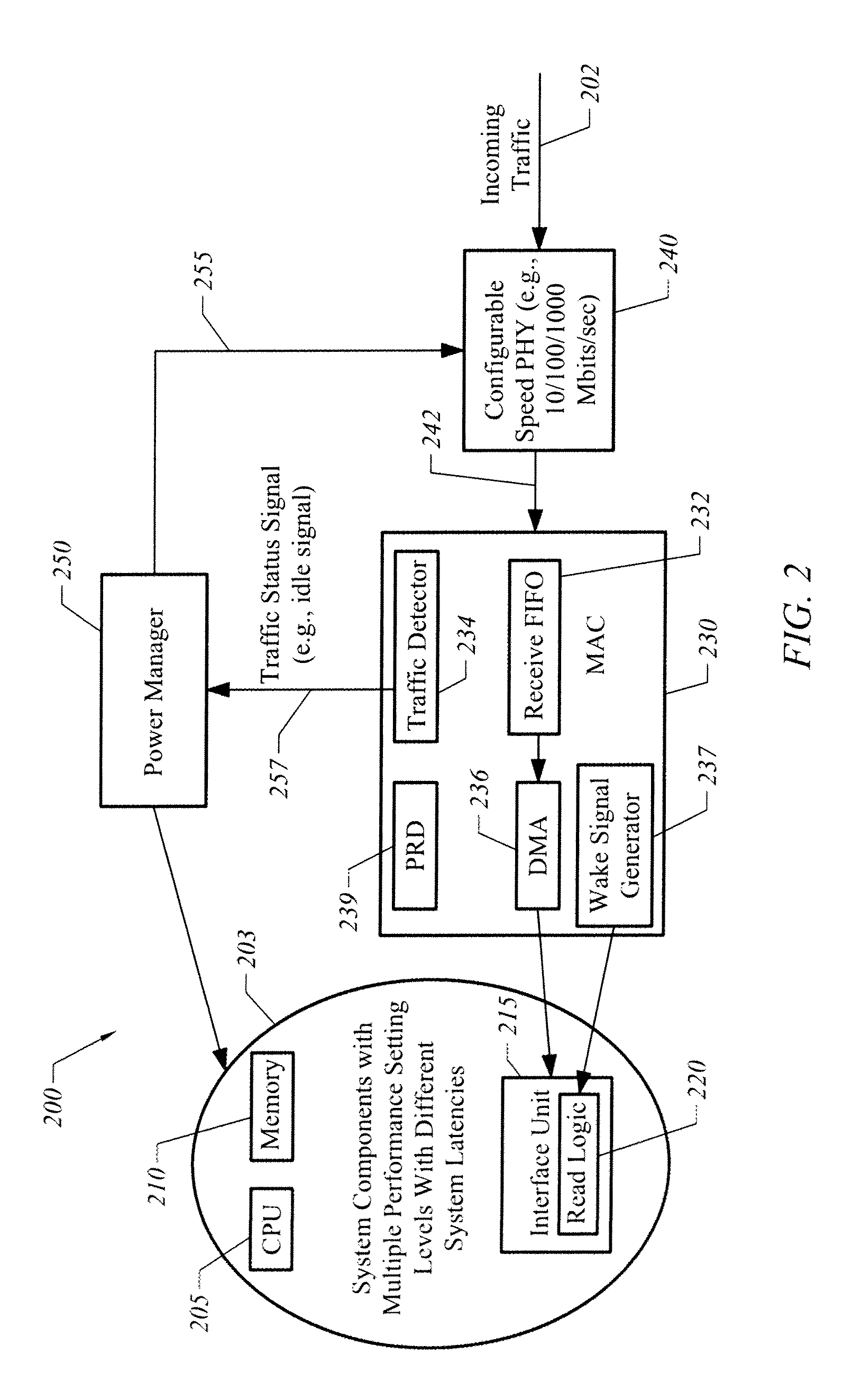
[0016]FIG. 2 illustrates a computing system 200 of the present invention. Computing system 200 is designed to be coupled to a network 202 such as a packet-based networks with an Ethernet network being one example of a packet-based network. A data receiving portion 203 of computing system 200 receives data from network 202 via MAC unit and may, for example include components to place incoming data into memory or an upstream link. Data receiving portion 203 may be implemented using different combinations of components to include a central processing unit, memory controller, and front side buses but in one exemplary implementation includes a central processing unit (CPU) 205, memory 210, and an interface unit 215 to support a CPU bus and an upstream link to memory 210. Interface unit 215 may, for example, have a bus or a bridge that includes a memory controller to access memory 210. Read logic 220 is provided in interface unit 215 to support read operations.

[0017]Data receiving portion...


PUM


Abstract

A system is coupled to a network by a network interface. In a power savings mode the speed setting of the network interface is reduced to accommodate increased system latency.

Description

FIELD OF THE INVENTION[0001]The present invention is generally related to techniques to save power in computing systems coupled to a network.BACKGROUND OF THE INVENTION[0002]Computing systems are often coupled to a packet-based network. For example, Referring to FIG. 1, a computing system 100 may be coupled to an Ethernet network by a network interface 130. The computing system 100 may, for example have a central processing unit 105 internal bus 110, memory controller 115, and memory 120. In a network environment bursts of traffic 160 can arrive at any time, depending upon the actions of other client systems (not shown) coupled to the Ethernet network.[0003]In some applications it is desirable to utilize computing system 100 as part of a “lossless” high speed (e.g., 1000 Mbit / s) network in which computing system 100 is designed to minimize data loss. That is, computing system 100 is designed and operated to avoid losing data packets in bursts of incoming traffic 160.[0004]One proble...

Claims


Application Information

Patent Timeline
IPC IPC(8): G06F15/16
CPCH04L12/12H04L69/24Y02B60/32Y02B60/35Y02B60/34Y02D30/50
Inventor GYUGYI, PAUL J.SURGUTCHIK, ROMANLUI, RAYMOND A.
Owner NVIDIA CORP
Why Eureka
Try Eureka