Exhaust system

a technology of exhaust system and exhaust pipe, which is applied in the direction of combustion types, machines/engines, lighting and heating apparatus, etc., can solve the problems of relative high temperature, reduce heat transfer, reduce heat flow to the fuel injector which is in the receiving body, and reduce heat flow

Active Publication Date: 2009-10-20
PUREM GMBH
View PDF15 Cites 30 Cited by
  • Summary
  • Abstract
  • Description
  • Claims
  • Application Information

AI Technical Summary

Benefits of technology

[0006]This invention is based on the general idea of reducing heat transfer from the exhaust line to the fuel injector. This is accomplished first by the fact that a flange by means of which a receiving body into which the fuel injector is inserted is mounted on the exhaust line, which is itself mounted on said receiving body via a constriction in cross section and additionally is achieved by the fact that said flange is mounted on the exhaust line via a thermal insulator. The two measures may be used cumulatively or alternatively. The thermal insulator prevents heat transfer from the hot exhaust line to the flange. In addition the constriction in cross section inhibits the transfer of heat from the flange to the receiving body. Through the inventive measures described here, the heat flow to the fuel injector which is in the receiving body can be reduced. In this way, active or passive cooling measures, for example, are better able to dissipate the heat, thereby reducing the risk of overheating of the fuel injector.
[0007]According to an advantageous embodiment, a cooling channel that extends coaxially with a longitudinal axis of the fuel injector in a ring shape may be integrated into the receiving body. This cooling channel is arranged in the receiving body in such a way that it surrounds a receiving section of the receiving body in which there extends a nozzle section of the fuel injector having at least one injector hole for injecting fuel. In this way, with the help of the actively cooled receiving body, the area of the fuel injector, namely said nozzle section which is exposed to the greatest thermal load during operation is cooled especially intensely and is thus prevented from overheating.
[0008]According to an advantageous embodiment, the receiving body may have, on a side facing away from the flange, a tension sleeve which surrounds the fuel injector at least partially coaxially with its longitudinal axis and which carries on an end section facing away from the flange a tension body which braces the fuel injector axially against the receiving body. Due to this design, fixation of the fuel injector on the receiving body is ensured in a particularly simple manner. In addition, due to the clamping of the fuel injector with axial contact faces between the fuel injector and the receiving body, a prestressed contact is achieved, which supports heat transfer and thereby improves the cooling effect of the receiving body which is preferably actively cooled.
[0009]In an advantageous refinement, the tension body may be supported axially on a connecting element which is in turn supported axially on the fuel injector and is connected to a fuel supply. This connecting element thus forms the connection of the fuel injector to the fuel supply and is tied in here to the mounting of the fuel injector such that the tension body makes it possible to secure both the connecting element on the fuel injector and the fuel injector in the receiving body.
[0010]An especially compact design is obtained when the tension body is designed in the form of a sleeve and is aligned coaxially with the longitudinal axis of the fuel injector and the fuel supply is connected axially through the tension body to the connecting element.

Problems solved by technology

It is problematical here that relatively high temperatures may occur in and / or on the exhaust line but at the same time the fuel injector must not exceed a certain maximum allowed operating temperature.

Method used


Image

  • Exhaust system
  • Exhaust system

Examples


Embodiment Construction

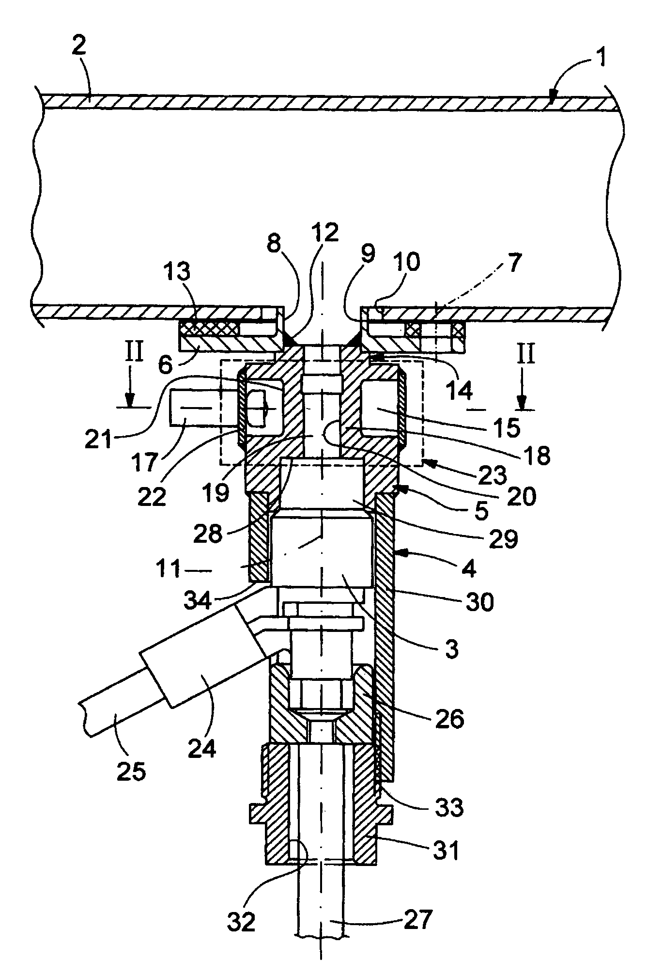
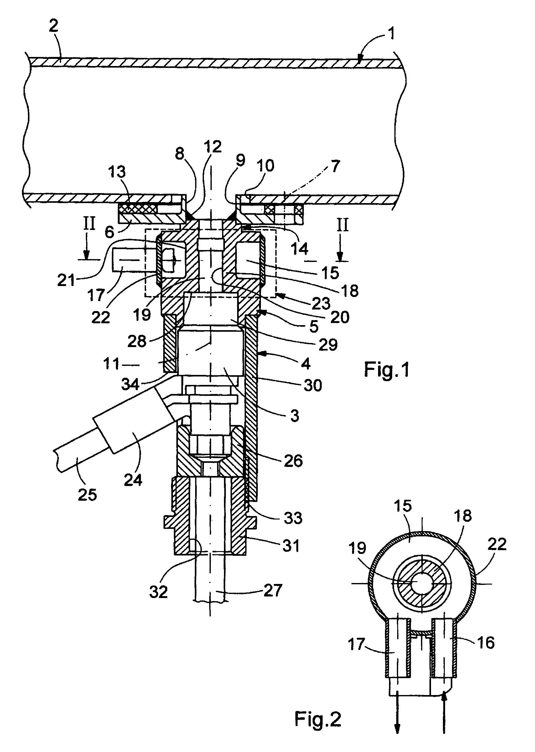
[0017]According to FIG. 1, an exhaust system 1 of an internal combustion engine (not shown here) which may be provided in a motor vehicle in particular has an exhaust line 2 which carries the exhaust gas generated during operation of the internal combustion engine away from the internal combustion engine. Accordingly, the exhaust line 2 is usually a pipe or the like, only a small detail of which is shown here.

[0018]The exhaust system 1 is also equipped with at least one fuel injector 3 with the help of which fuel may be injected into the exhaust line 2. Such a fuel injection may be performed—if it is done upstream from an oxidation catalytic converter—to increase the temperature of the exhaust, e.g., in order to regenerate or desulfate an NOX storage catalytic converter.

[0019]The fuel injector 3 is mounted on the exhaust line 2 via a mounting device 4. The mounting device 4 includes a receiving body 5 and a flange 6 by which the receiving body 5 is mounted on the exhaust line 2. To ...


PUM


Abstract

The present invention relates to an exhaust system for an internal combustion engine, in particular in a motor vehicle, having an exhaust line carrying exhaust gas away from the internal combustion engine and having a fuel injector for injecting fuel into the exhaust line. The fuel injector is mounted on the exhaust line via a mounting device. This mounting device has a receiving body into which the fuel injector is inserted and which is mounted on the exhaust line via a disk-shaped flange. To reduce the risk of overheating of the fuel injector, the flange is mounted on the receiving body via a constriction in cross section and / or on the exhaust line via a thermal insulator.

Description

[0001]This application claims foreign priority of German Patent Application No. DE 10 2004 056 791.3, filed Nov. 24, 2004 in Germany, which application is incorporated herein by reference in its entirety.FIELD OF THE INVENTION[0002]The present invention relates to an exhaust system for an internal combustion engine, in particular in a motor vehicle.BACKGROUND OF THE INVENTION[0003]Exhaust systems usually includes an exhaust line that carries the exhaust away from the internal combustion engine. In certain applications, it may be necessary to inject fuel into the exhaust line in addition. For example, the injection of such a secondary fuel upstream from an oxidation catalytic converter can greatly increase the exhaust temperature, e.g., to trigger regeneration of a particulate filter. For injection of fuel into the exhaust line, the exhaust system may be equipped with at least one fuel injector which is mounted on the exhaust line via a suitable mounting device. Essentially such a fu...

Claims


Application Information

Patent Timeline
Patent Type & Authority Patents(United States)
IPC IPC(8): F01N3/00
CPCF01N3/2066F01N2260/02Y02T10/24F01N2610/1453F01N2610/11Y02A50/20Y02T10/12
Inventor HANITZSCH, ROBERTRUDELT, JOSEF
Owner PUREM GMBH
Why Eureka
Try Eureka