Secondary fuel injection from stage one nozzle

Inactive Publication Date: 2009-10-20
GENERAL ELECTRIC CO
View PDF24 Cites 72 Cited by
  • Summary
  • Abstract
  • Description
  • Claims
  • Application Information

AI Technical Summary

Benefits of technology

[0009]The present application further describes a method of reducing NOX emissions in a gas turbine engine. The method may include combusting a primary stream of fuel and a primary stream of air to create a hot gas stream, flowing the hot gas stream towards a number of stage one nozzles, flowi

Problems solved by technology

Although testing of this secondary combustion system has shown promise in reducing overall NOX emissions, such a system has not been widely adopted because of a concern with

Method used


Image

  • Secondary fuel injection from stage one nozzle
  • Secondary fuel injection from stage one nozzle

Examples


Example

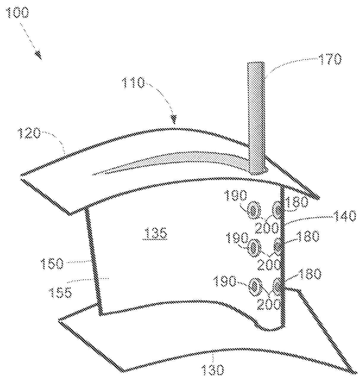
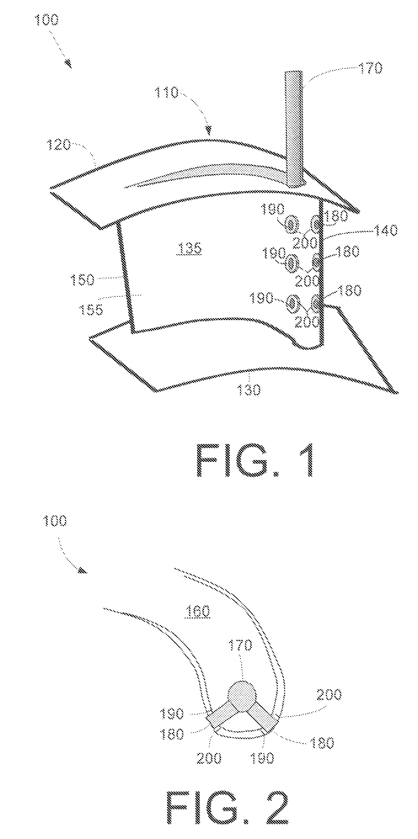
[0013]Referring now to the drawings, in which like numerals refer to like elements throughout the several views, FIGS. 1 and 2 show a secondary combustion system 100 as is described herein. The secondary combustion system 100 is positioned within some or all of the stage one nozzles 110, one of which is shown in FIGS. 1 and 2. The stage one nozzles 110 are the nozzles closest to the combustor and the primary combustion system. Each stage one nozzle includes an outside diameter 120 and an inside diameter 130. Each stage-one nozzle 110 also includes an airfoil 135 having a leading edge 140, a trailing edge 150 and an outer surface 155. A cooling cavity 160 extends within the stage one nozzle 110.

[0014]The secondary combustion system 100 includes a supply tube 170. The supply tube 170 enters the stage one nozzle 110 from the outside diameter 120 and extends into the cooling cavity 160. The supply tube 170 leads to a number of injectors 180. As is shown in FIG. 2, the individual injecto...


PUM


Abstract

A secondary combustion system for a stage one turbine nozzle. The secondary combustion system may include a supply tube extending into the stage one nozzle, a number of injectors extending from the supply tube to an outer surface of the stage one nozzle, and an air gap surrounding each of the number of injectors.

Description

TECHNICAL FIELD[0001]The present application relates generally to gas turbine engines and more particularly relates to a secondary fuel injection system positioned about the stage one nozzles.BACKGROUND OF THE INVENTION[0002]One method used to lower overall NOX emissions in a gas turbine engine is to minimize the reaction zone temperature below the level at which NOX emissions are formed. For example, commonly owned U.S. Pat. No. 6,868,676 to Haynes, entitled “Turbine Containment System and Injector Therefore”, shows the use of a secondary combustion system downstream of the primary combustion system. This secondary combustion system includes a number of injectors to inject fuel and other fluids at the head end of the combustor. The fuel burns quickly due to the high temperature environment and relieves the temperature of combustor head end so as to lower overall NOX emissions. U.S. Pat. No. 6,868,676 is incorporated herein by reference.[0003]Although testing of this secondary combu...

Claims


Application Information

Patent Timeline
IPC IPC(8): F02C3/16
CPCF23R3/34F23R3/20F23C2900/07001F02C7/26F02C7/22
Inventor WIDENER, STANLEY KEVINDAVIS, JR., LEWIS BERKLEY
Owner GENERAL ELECTRIC CO
Why Eureka
Try Eureka