Sealing arrangement for a hydraulic plug-in connection

a technology of sealing arrangement and plug-in connection, which is applied in the direction of fluid pressure sealing joints, pipe elements, couplings, etc., can solve the problems of separation of sealing elements from sleeves, inability to pull sealing elements out, etc., and achieve the effect of facilitating the transverse insertion of sealing elements

Active Publication Date: 2009-10-20
FTE AUTOMOTIVE GMBH & CO KG
View PDF17 Cites 11 Cited by
  • Summary
  • Abstract
  • Description
  • Claims
  • Application Information

AI Technical Summary

Benefits of technology

[0007]According to the basic concept of the invention, the sealing element is not combined with the sleeve in the axial direction as in the two sealing arrangements according to the prior art outlined in the introduction, but rather the complementary shaped profiles of sealing element and sleeve enter into form-fitting engagement as a result of being pushed in from the side, transversely to the axis of the sleeve. As a result of this design, the sealing element cannot be pulled out and separated from the sleeve when the plug-in fitting is pulled out of the socket. There is also no damage to the sealing element caused by pulling the plug-in fitting out of the socket. Moreover, when the sealing element is combined with the sleeve, only relatively small elastic deformations of the sealing element are necessary in order to captively fix the sealing element on the sleeve.
[0008]Preferably, the transverse recess of the sleeve, which sleeve is hollow-cylindrical at its sealing-element-side end and ends with an annular end face arranged perpendicular to the axis of the sleeve, is formed of an outer and an inner recess section, of which the outer recess section is a longitudinal slot which starts from the annular end face and runs diametrically through the sleeve, the wall surfaces of this longitudinal slot running parallel to one another and to the axis of the sleeve, while the inner recess section is a transverse slot which runs parallel to the annular end face through the sleeve, the transverse dimension of said transverse slot being larger than the distance between the wall surfaces of the longitudinal slot, so that the transverse recess in the sleeve essentially has a T-shaped structure. Here, the fixing body of the sealing element is designed in terms of its shape and dimensions such that it corresponds to the outer and inner recess sections of the transverse recess of the sleeve. In this way it is possible to achieve undercut surfaces of considerable size which are directed transversely to the pull-out direction of the plug-in fitting, which surfaces, on account of the fixing body of complementary design, securely hold the sealing element on the sleeve so as to withstand even high pull-out forces in the axial direction. With this design of sleeve and sealing element, the plug-in fitting can be frequently pulled out of the socket and reconnected to the latter without separation of the sealing element from the sleeve and without any risk of damage to the sealing element and also without any impairment in the sealing action.
[0010]Continuing the concept of the invention, the inner diameter of the annular end face of the sleeve, which end face is interrupted by the outer recess section at diametrically opposite points, may be larger than the inner diameter of the sleeve which corresponds to the outer diameter of the hydraulic line, wherein two opposite concave cylindrical wall section surfaces are formed concentrically to the axis of the sleeve between in each case two wall surfaces of the outer recess section, the installed sealing element bearing against said concave cylindrical wall section surfaces with corresponding convex cylindrical wall section surfaces of its fixing body, wherein two opposite thin-walled wall sections are formed between the convex cylindrical wall section surfaces of the sealing element and the inner peripheral surface of the sealing element, said thin-walled wall sections being able to be elastically deformed upon insertion of the fixing body of the sealing element into the undercut transverse recess, as a result of which the sealing element is fixed to the sleeve. With this design of the sleeve and of the sealing element, two thin-walled, outwardly convex wall sections are thus formed on the fixing body of the sealing element, which convex wall sections are elastically deformed during installation of the sealing element on the sleeve and bear against correspondingly concave wall section surfaces of the sleeve when the fixing body of the sealing element has been fully introduced transversely into the sleeve, and in this way help to captively fix the sealing element on the sleeve in the transverse direction too.
[0011]Finally, during installation of the sealing element on the sleeve, the sealing element is firstly guided on two opposite wall surfaces of the outer recess section of the sleeve with corresponding wall surfaces of its fixing body, before the thin-walled wall sections are subjected to elastic deformation between two parallel wall surfaces of the outer recess section of the sleeve. As a result of the particular design of the outer recess section as a longitudinal slot, guide surfaces are thus formed on the sleeve which, in conjunction with corresponding surfaces on the fixing body of the sealing element, facilitate the transverse insertion of the sealing element and aid automatic assembly.

Problems solved by technology

As a result of this design, the sealing element cannot be pulled out and separated from the sleeve when the plug-in fitting is pulled out of the socket.

Method used


Image

  • Sealing arrangement for a hydraulic plug-in connection
  • Sealing arrangement for a hydraulic plug-in connection
  • Sealing arrangement for a hydraulic plug-in connection

Examples


Embodiment Construction

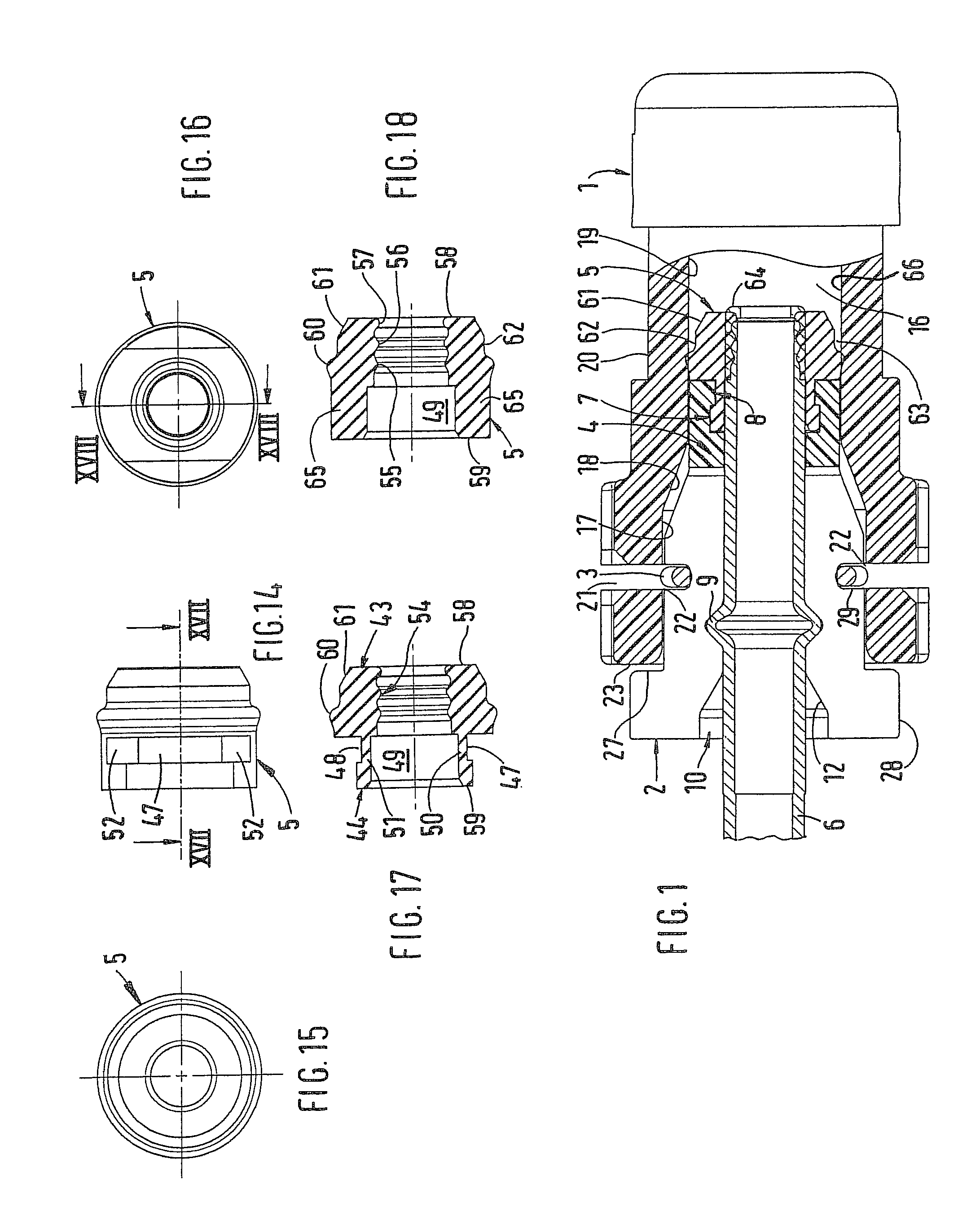
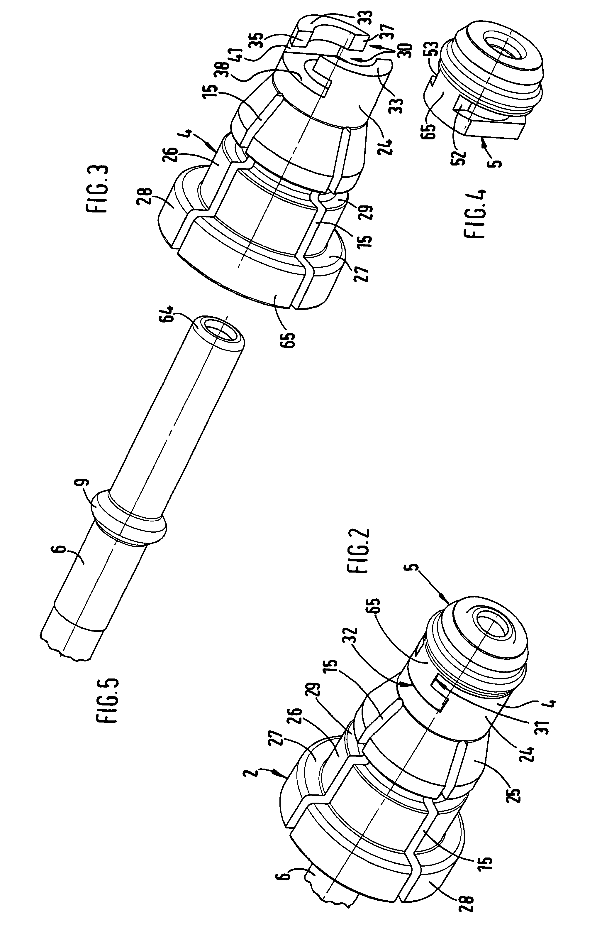
[0031]The hydraulic plug-in connection shown in FIG. 1 consists of a socket 1 and a plug-in fitting 2 which is connected thereto and which can be releasably fixed in a sleeve 4 by means of a securing element 3 made of spring steel wire. The socket 1 may be the connection piece to a hydraulic unit, for example a cylinder housing, or else a bushing which connects two hydraulic lines.

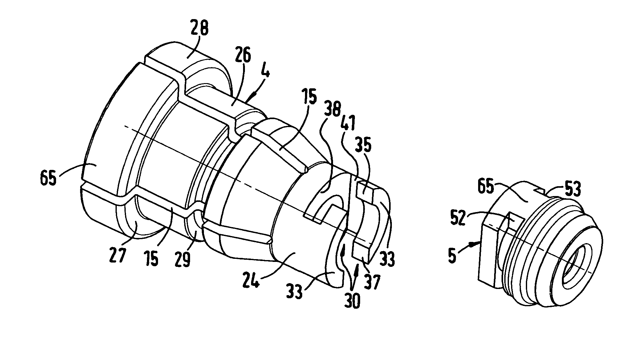
[0032]The plug-in fitting 2 comprises an elastic sealing element 5 for sealing off the plug-in connection with respect to the exterior, and the sleeve 4 which is attached to a hydraulic tube 6 of a hydraulic line. A shaped profile 7, which will be described in more detail below, is formed on the sealing element and serves for form-fitting engagement with a complementary shaped profile 8 on the sleeve 4, which will also be described in more detail below, so as to undetachably fix the sealing element 5 on the sleeve 4.

[0033]As can be seen from FIGS. 1, 5, 6 and 9, a flange 9 is formed on the hydraulic tube 6...


PUM


Abstract

A sealing arrangement for a hydraulic plug-in connection for use in particular in the motor vehicle industry for hydraulic clutch and brake systems is fitted on a hydraulic plug-in connection and has a socket and a plug-in fitting which can be connected thereto. The plug-in fitting is attached to a hydraulic tube. The plug-in fitting has a sleeve and a sealing element fixed thereto, which seals off the plug-in connection both from the hydraulic tube and from the exterior of the socket. The sealing element and the end of the sleeve which receives the sealing element are designed so as to be able to install the sealing arrangement without it being possible for the sealing element to be separated axially from the sleeve when the plug-in connection is released.

Description

FIELD OF THE INVENTION[0001]The invention relates to a sealing arrangement for a hydraulic plug-in connection, in particular for use in the motor vehicle industry for hydraulic clutch and brake systems.DESCRIPTION OF PRIOR ART[0002]In a known sealing arrangement (DE-A-197 14 801) for a hydraulic plug-in connection, a sealing element has on its inner peripheral surface a shaped profile which serves for form-fitting engagement with a shaped profile formed on the outer peripheral surface of a sleeve, in order to fix the sealing element to the sleeve. When the sealing element is installed by pushing it axially onto the associated end of the sleeve, the sealing element is partially widened elastically in order to bring the two shaped profiles into form-fitting engagement. This pre-assembly of the plug-in fitting is intended to captively fix the sealing element on the sleeve.[0003]Once the plug-in fitting has been attached to a hydraulic line, the plug-in connection is established by inse...

Claims


Application Information

Patent Timeline
Patent Type & Authority Patents(United States)
IPC IPC(8): F16L17/00
CPCF16L37/144F16L37/088F16L37/0885F16D2048/0224
Inventor ELFLEIN, STEPHENVOGEL, ALBERT
Owner FTE AUTOMOTIVE GMBH & CO KG
Why Eureka
Try Eureka