High speed transmission connector

a high-speed transmission and connector technology, applied in the direction of fixed connections, coupling device connections, protective earth/shielding arrangements, etc., can solve the problems of complex conductor pattern connecting the two, further complicating the conductor pattern, and reducing the transmission time difference so as to achieve significant reduction of cross-talk between parallel signal contact pairs

Inactive Publication Date: 2009-10-20
FUJITSU COMPONENENT LTD
View PDF7 Cites 25 Cited by
  • Summary
  • Abstract
  • Description
  • Claims
  • Application Information

AI Technical Summary

Benefits of technology

[0009]It is an object of the present invention to provide a high speed transmission connector including a plurality of signal contact pairs respectively constituting balanced transmission lines, wherein a difference in signal transmission time can be reduced as much as possible, wherein a conductor pattern on a circuit board can be simplified when the connector is mounted on the circuit board, and wherein a signal contact unlikely to produce a disturbance in a magnetic field is used.
[0011]In accordance with the above invention, since the board connecting sections of all the signal contacts are disposed along the first lateral surface of the body, when the high speed transmission connector is to be connected to another electronic part disposed in close proximity of the lateral surface of the body on the circuit board, for example, the conductor pattern connecting the two can be simplified. In addition, since the region between the board connecting section and the attaching section can be formed in a non-roundabout shape, the problem encountered in prior art, in that the signal transmission characteristics may deteriorate due to a magnetic field disturbance arising from the curved portion with small radius of curvature, can be reliably avoided. Further, in spite of the difference in the length of the relevant regions of a pair of signal contacts from each other, the difference in transmission time of the signal contact pair can be minimized as much as possible by covering the shorter region with a material of higher dielectric constant (specific inductivity) and the longer region with a material of lower dielectric constant (specific inductivity).
[0012]In the above-described high speed transmission connector, a material covering at least one of the regions of the pair of signal contacts may be a part of the body. In this arrangement, the material for covering at least one region of a pair of signal contacts can be prepared easily.
[0013]Alternatively, a material covering one of the regions of the pair of signal contacts may be air. In this arrangement, the material for covering one region of a pair of signal contacts can be easily provided.
[0015]Each of the plurality of ground contacts may be provided with a pair of contacting sections at one longitudinal end for a conductive contact with a corresponding ground contact of a counterpart connector, a pair of board connecting sections at another longitudinal end for a connection with a grounding potential on a circuit board, and an attaching section between the contacting sections and the board connecting sections for an attachment to the body; and all of the board connecting sections of the ground contacts may be disposed respectively along the first lateral surface and a second lateral surface of the body, opposite to the first lateral surface; and wherein each of the plurality of ground contacts is shaped in such a manner as to conceal the pair of signal contacts of each of the plurality of signal contact pairs as seen in a direction of the parallel array, when the plurality of signal contact pairs and the plurality of ground contacts are disposed at proper positions on the body. In accordance with this structure, cross talk between parallel signal contact pairs can be significantly reduced.

Problems solved by technology

Thus, when the high speed transmission connector is to be connected, on the circuit board, to another electronic component disposed, for example, in close proximity to one of the lateral surfaces of the body, a conductor pattern connecting the two may become complicated depending on the relative position between the connector and the electronic part.
As a result, this may further complicate the conductor pattern.
However, with this configuration, in each signal contact pair, one of the signal contacts has shorter spatial distance between the contacting section and the board connecting section than that of the other signal contact, and this may leads to a problem of difference in signal transmission time in balanced transmission.
However, this may lead to another problem that, in such a contact having curved portion with small radius of curvature, the signal transmission characteristics may deteriorate due to a magnetic field disturbance that may arise from the curved portion.

Method used


Image

  • High speed transmission connector
  • High speed transmission connector
  • High speed transmission connector

Examples


Embodiment Construction

[0023]The embodiments of the present invention are described below in detail, with reference to the accompanying drawings. In the drawings, the same or similar components are denoted by common reference numerals.

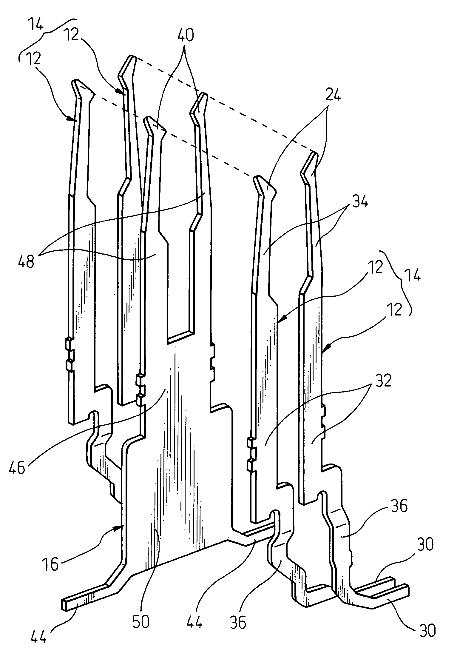
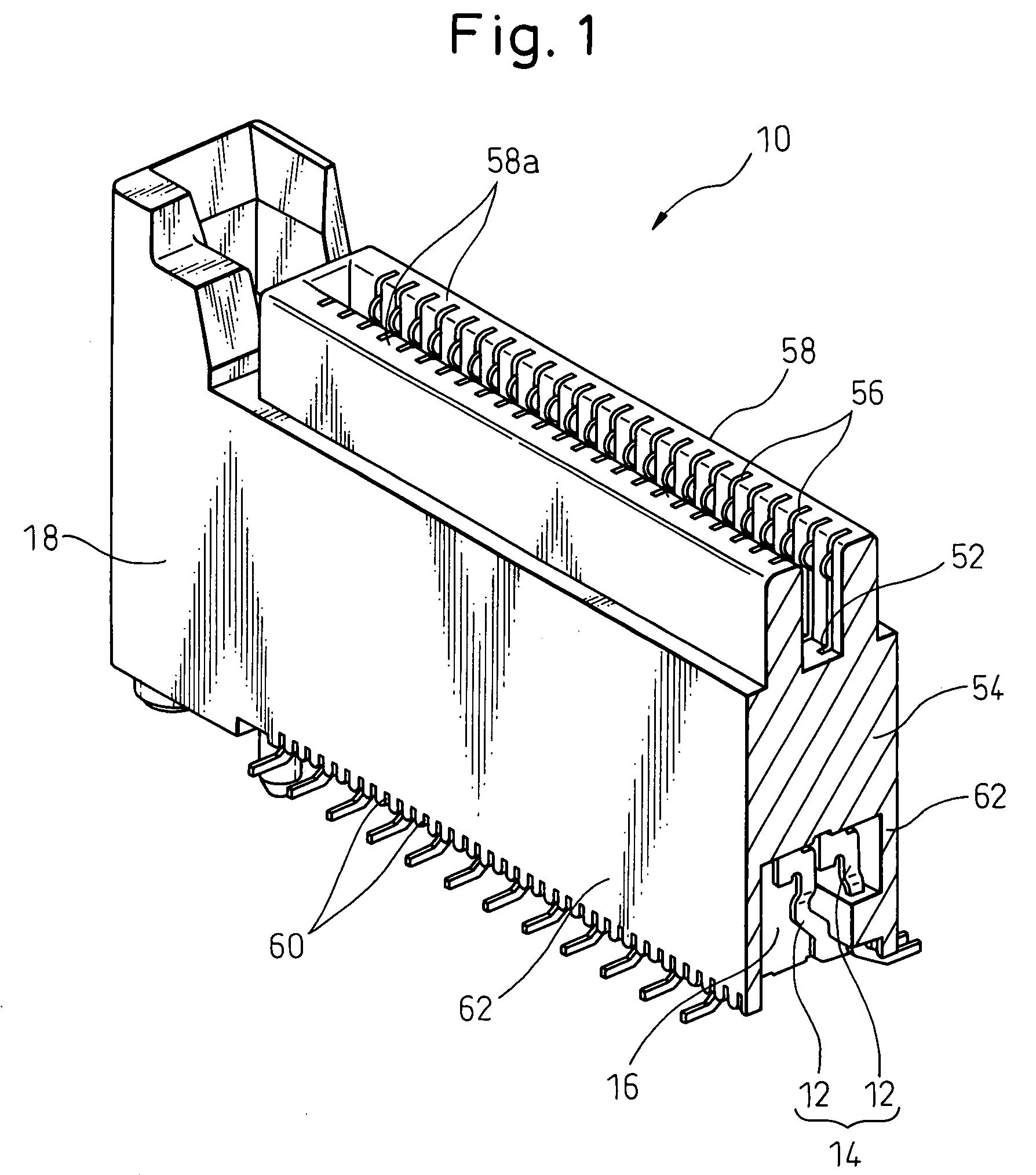
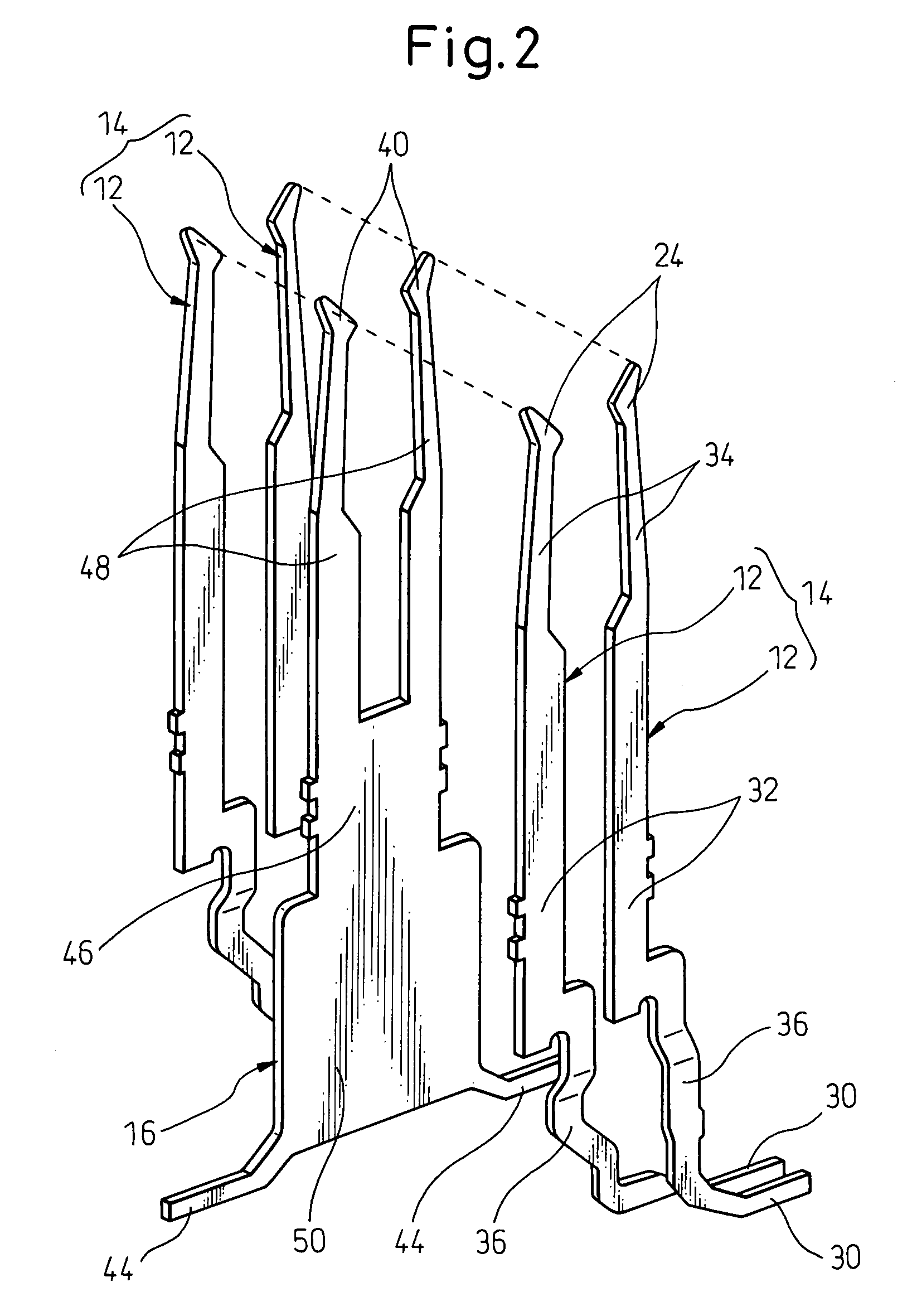
[0024]Referring to the drawings, FIG. 1 is a perspective view showing a high speed transmission connector 10 according to an embodiment of the present invention, FIG. 2 is a perspective view showing a contact of the high speed transmission connector 10, FIGS. 3 and 4 are views schematically showing the connecting configuration of individual contacts and another conductor, FIG. 5 is an enlarged perspective view showing a main characteristic portion of the high speed transmission connector 10, and FIG. 6 is an enlarged sectional view showing the same characteristic portion. The high speed transmission connector 10 is used as a balanced transmission (or a differential transmission) connector, for example, in a computer, server, exchanger, router, etc.

[0025]As shown in FIG. 1, t...


PUM


Abstract

A high speed transmission connector including several signal contact pairs arranged in a parallel array, each including a pair of signal contacts constituting a balanced transmission line; several ground contacts, each being arranged between two signal contact pairs arranged in the parallel array; and an electro-insulating body supporting the signal contact pairs and the ground contacts. Each signal contact is provided with a contacting section at one longitudinal end for conductive contact with a corresponding signal contact of a counterpart connector, a board connecting section at another longitudinal end for connection with a conductor on a circuit board, and an attaching section between the contacting section and the board connecting section for an attachment to the body. All of the board connecting sections of the signal contacts are disposed along a first lateral surface of the body. The signal contacts of the signal contact pairs are individually covered, at least partially, by materials having dielectric constants different from each other, in certain regions defined between board connecting sections and attaching sections.

Description

BACKGROUND OF THE INVENTION[0001]1. Field of the Invention[0002]The present invention relates to a high speed transmission connector.[0003]2. Description of the Related Art[0004]A high speed transmission connector, including a plurality of signal contact pairs which are arranged in a parallel array and each of which includes a pair of signal contacts constituting a balanced transmission line, a plurality of ground contacts which are arranged alternately relative to the signal contact pairs and each of which is arranged between two of signal contact pairs arranged in the parallel array, and an electro-insulating body which supports the signal contact pairs and the ground contacts in a mutually insulated arrangement, is conventionally known (see, e.g., Japanese Patent No. 3685908). In this configuration, a signal contact pair constituting a balanced transmission line which is unlikely to be affected by noise is used, and in addition, cross talk between adjacent signal contact pairs is...

Claims


Application Information

Patent Timeline
Patent Type & Authority Patents(United States)
IPC IPC(8): H01R24/00H01R12/51H01R12/55H01R13/6474H01R13/6477H01R13/658H01R13/6585
CPCH01R12/716H01R23/688H01R13/6585
Inventor AKAMA, JUNICHIKUMAMOTO, TADASHIKONDO, TAKAHIROTANAKA, YOKOKOBAYASHI, MITSURU
Owner FUJITSU COMPONENENT LTD
Why Eureka
Try Eureka